Hi all,
I’m putting together a small class D amp setup for my home office.
The topology is:
SMPS (24v) —— isolated 5v buck supply — Arylic wifi streaming receiver
—— TPA3116 board (x2)
—— miniDSP
I am getting some digital interference caused by having both the SMPS and buck supply meanwell SPBW06G-05 Blockedconnected.
If i run the Arylic from an external usb supply, there is no interference. I have been running everything off of a 12v 5A SMPS for testing.
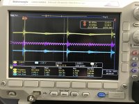
The attached scope capture shows the input to the buck supply (yellow trace), the output of the supply (blue trace) and the single-ended audio output from the Arylic.
It is quite obvious that the 600kHz switching frequency of the buck supply is being passed both upstream and downstream. It is also visible in the audio signal.
I have tried a variety of filters to get rid of this signal. I have tried LR (4.7 uH, 3.3ohm) and LC filters (4.7 uH, 50nF) on either side of the buck converter but neither seems to have any effect.
Unfortunately the only inductor i have in my parts stash that can handle the current (1A) is the 4.7uH sumida CDRH5D28RHPNP-4R7NC Blocked.
I can probably go grab something else from the office, but i would need to know what specs...
What am I missing here? I’m sure this is easy but for some reason it is getting past me.
I’m putting together a small class D amp setup for my home office.
The topology is:
SMPS (24v) —— isolated 5v buck supply — Arylic wifi streaming receiver
—— TPA3116 board (x2)
—— miniDSP
I am getting some digital interference caused by having both the SMPS and buck supply meanwell SPBW06G-05 Blockedconnected.
If i run the Arylic from an external usb supply, there is no interference. I have been running everything off of a 12v 5A SMPS for testing.
The attached scope capture shows the input to the buck supply (yellow trace), the output of the supply (blue trace) and the single-ended audio output from the Arylic.
It is quite obvious that the 600kHz switching frequency of the buck supply is being passed both upstream and downstream. It is also visible in the audio signal.
I have tried a variety of filters to get rid of this signal. I have tried LR (4.7 uH, 3.3ohm) and LC filters (4.7 uH, 50nF) on either side of the buck converter but neither seems to have any effect.
Unfortunately the only inductor i have in my parts stash that can handle the current (1A) is the 4.7uH sumida CDRH5D28RHPNP-4R7NC Blocked.
I can probably go grab something else from the office, but i would need to know what specs...
What am I missing here? I’m sure this is easy but for some reason it is getting past me.
Attachments
Last edited:
This looks more like ground-noise, since it is idenmtical on each trace.
do connect the buck via 2 twisted wires with several turns thru a ferrite ring or cylinder (you find on old usb cables) directly to the input cap of the converter.
do not ground it anywhere.
Go directly twisted pair from the isolated output to your digital board where you had connected the 5V voltage. no grounding here either that is already done on the board.
Go also directly from the 24V twisted to the amp.
Last edited:
If you haven't looked into the SMPS filter project by Mark Johnson, it might be exactly what you need.
Sorry I don't remember the name of the thread.
Cheers
Sorry I don't remember the name of the thread.
Cheers
You will most of the time measure such noise in the vicinity of switched gear. As long as you do not hear interference you can ignore it. So do you hear interference noise? The oscilloscope is a nice and useful tool - but it measures things you cannot hear - like switchnoise - on the other side you may hear things like crossover distortion that you do not see on you scope. Measuring switched noise opens a can of worms and needs accurate interpretion.
Last edited:
Make sure you are measuring correctly. If you're using the scope probes ground clip you're picking up EMI and interpreting it as conducted noise. Proper technique here https://www.google.com/url?sa=t&sou...FjAdegQISBAB&usg=AOvVaw1mrH29DbJv1eEiZJRl8Fex
I will definitely check out that smps thread. I think ii need the ‘tribal knowledge’ on this one. Everywhere i search, i find only theory, which is nice but I don’t have complete enough specs to do all of the calculations.
Yes, it is audible noise. it is almost like a digital “ppppt.....pppppt” very electronic sounding, not hum or static I think it must be some beat frequency or overtone of the switching frequencies because it is about 2Hz. It isn’t directly visible on the scope, but when i swap out to the usb power supply, the sound goes away and all of the power rails calm down. I will record it and post a youtube.
All of the boards are sitting on a single sided copper pcb (copper side down) that i have used as a “ground plane” to produce a low impedance return path. Nice and hum free! The buck regulator is currently sitting on a breadboard next to the setup, but it is connected directly to the dc input jack.
Attachments

Here is the recording. Of course, just like taking your car to the repair shop, it was barely making the sound when i sat down to record it. But if you listen closely, you will hear the 2hz ‘pt...pt....pt...pt’
Interference - YouTube
Interference - YouTube
Another idea, do you have an idea what your actual load is vs. the supply's rating? You could be in a pulse skipping mode or discontinuous mode which can make more noise. This is especially likely if the load is a small fraction(<10%) of the supply's maximum output. Try adding a load with whatever resistor you can grab and see if the noise is affected.
Oh Super interesting idea. Yea, I have no idea what kind of load it is doing. I'm not playing music through it, so I'm sure everything is super low.
Load to which device? (do you think it is the SMPS or the buck converter that is in pulse skipping mode?)
Load to which device? (do you think it is the SMPS or the buck converter that is in pulse skipping mode?)
How much of a load are you thinking it should need? 100mA or something?
The buck converter is actually powering the receiver module that is communicating over wifi (although i’m sure it is is optimized to not be constantly drawing power).
The buck converter is actually powering the receiver module that is communicating over wifi (although i’m sure it is is optimized to not be constantly drawing power).
I would say try something more like 25 to 50% if you can. Otherwise just grab what you have handy and see if anything changes...
Yup, the interference gets much worse with more load. Good suggestion. I’m now thinking it is a current effect more than a voltage effect.
My cousin (an EE) and i tried a few scenarios yesterday. We tried adding bulk caps to the input and output of the buck supply and also to the inout of the board being powered by the buck supply. No significant effect. So we figured that the sound was not being caused by ‘starvation’ of the arylic board. Recall that when powering the arylic board from an external supply, there is no interference.
We removed the wifi module from the Arylic board and the interference disappeared (we figured this was the largest power consumer).
The prevailing theory now is that there is a resonance between the buck supply and the SMPS.
Swapping out the smps for a different smps doesn’t change it, but powering by the linear bench supply solves the problem.
I’m going to try powering the arylic board with an LDO instead of the buck supply and see if that makes a difference.
Hi Bansuri, We have it connected exactly as you recommend. Although I forgot to add the ferrite ring. I will do that next!
- Home
- Amplifiers
- Power Supplies
- What am I doing wrong..? SMPS driving a buck converter :(