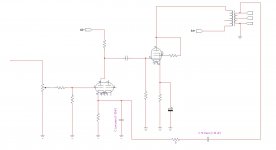
Hello, I've tested with very good sonic results, that I can flat the frequency amplifier response to less than -0.5 db in 20-20khz range if I put a pass band GNF. Overall the bass is very good just to include the C in the range of few microfarad.
What you think about this selective band feedback ?: I think it both enhances presence and low bass and increase the amplifier stability, so all pros and I don't see any cons, overall because ears don't recognise distortion below the 100-50 Hz.
I don't see this C Hi pass capacitor in any schematics...😕
The two capacitors values must be found with a spectrum analyzer, of course till to reach flat response, because it needs to correct the transformer curve first, which is out of any calculation or simulation.
Attachments
Removing feedback at low frequencies will raise output impedance and so cause bass peaking at the speaker bass resonance. This is already a problem with many SETs so perhaps not a good idea to make it worse? However, some people like this one-note bass and prefer it to real bass.
Maybe. We know he is not interested in hi-fi sound, as his website tells us that he uses CC resistors for a "mellow vintage sound-stage".
Doing such a thing can conduct to the amplifier, to become a powerful oscillator, by virtue of the phase alterations in the feedback path.
Not clear what you mean, but I suspect it enhances your speaker's response and/or speaker/room response.I think it both enhances presence and low bass
I have seen this method used in a few low end consoles. It's a reasonable way to deal with cheap,undersized, and poor bandwidth transformers. It can increase total bandwidth and stability by reducing feedback where the transformer's phase shift becomes a problem.
I have seen this method used in a few low end consoles. It's a reasonable way to deal with cheap,undersized, and poor bandwidth transformers. It can increase total bandwidth and stability by reducing feedback where the transformer's phase shift becomes a problem.
Exactly! Thanks

My OT is probably far from ideal...But I don't see the problem, or make stuff worse as the majority of SET are designed without GNF: so which is better between no GNF and a middle band GNF like this? The mentioned bass response issues will be equal in both cases.
If GNF is low (>- 12dB) you don't have any oscillation at LF at all. At HF margin phase is even improved than using the full band GNF.
The difficult stuff is to select the two C values, for which you need a good model simulator or a decent analyser, to make the curve flat.
Actually, if you route global NFB around the OPT, the OPT itself already forms a band pass filter in the NFB loop. Why anyone would add another band pass filter in the NFB loop totally escapes me.What about a pass band feedback in SET amplifier?
Actually, if you route global NFB around the OPT, the OPT itself already forms a band pass filter in the NFB loop. Why anyone would add another band pass filter in the NFB loop totally escapes me.
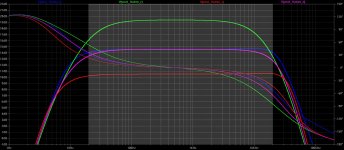
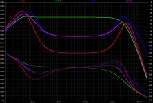
Maybe the graph better explains.
Concentrate on the gray area (20-20KHz)
1) green: no GNF
2) pink: -5dB GNF no Cap
3) blue: -5dB GNF plus Cap_Hi (2.4uF) plus Cap_Low (6.8nF)
4) red: -9dB GNF no Cap
So (3,blue) and (4,red) have the best extension in the 20-20KHz, but (3, blue) has more gain, more stability at HF and less GNF than (4,red) [for the folks who hate GNF sound].
Attachments
Last edited:
I see you simulated your amp in spice, and understand the idea and curves pretty well.
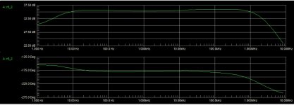
Can you post the same four graphs, but taken at the output tube's grid, and not the 16R tap of the OPT?
Cheers, GB
Can you post the same four graphs, but taken at the output tube's grid, and not the 16R tap of the OPT?
Cheers, GB
I see you simulated your amp in spice, and understand the idea and curves pretty well.
Can you post the same four graphs, but taken at the output tube's grid, and not the 16R tap of the OPT?
Cheers, GB
Hello, here's to you, at the input grid of the KT77, if I'm correct. I'm curious now to know the purpose. Thanks! GG
Attachments
Doesn't seem that odd to me. Most RIAA networks work by varying feedback with frequency to get the desired response shape, you're using the same idea to EQ a transformer that is weak in the bass. If you want SET and want to use that transformer, seems a decent compromise.
I tried a small lo-cap in the feed back loop of a low power SET that used a mains transformer for the opt a couple of years ago...and I remember liking the effect for a very brief amount of time. Tried it just for the experience then as soon as I did A vs B listening tests with conventional feedback the 10n cap went back in the bag.
Just my experience though
TM
Just my experience though
TM
Thanks for the diagrams. It just shows, to flatten the amp's output at the extremes of the bandwitdh, you need to up the signal at the extremes at both low/hi freq's. Yes, your band pass network works as intended, but you would just achieve the same by increasing the nfb by about 1~2 dB (which is a better alternative overall).Hello, here's to you, at the input grid of the KT77, if I'm correct. I'm curious now to know the purpose. Thanks! GG
I tried a small lo-cap in the feed back loop of a low power SET that used a mains transformer for the opt a couple of years ago...and I remember liking the effect for a very brief amount of time. Tried it just for the experience then as soon as I did A vs B listening tests with conventional feedback the 10n cap went back in the bag.
Just my experience though
TM
Thanks for the contribution! Be aware that just a couple of nanofarads capacity move the curve by nearly 1dB. Also the peak will move between MF (1kHz) and HF (20kHz).
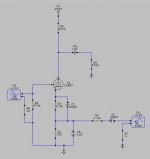
Also, adding a R_serie of few kohms in series to the Cap_Low (Rc would be in parallel to the cathode resistor), will change the curve with a MF hunce: you have built a simple but efficient "presence boost" equalizer filter!
So you did well to make a sort of blind test comparison between the two solutions (that's my preferred way to operate too when I have to test, by using a unique good reference amplifier), but you also need to test a dozen of caps in the range of 1nF to 15 nF before getting the best by ear.
Because this kind of HF filter, which is set in the feedback network, not only changes the frequency curve, but also changes dynamic, distortion, presence, 3D image, output impedance and damping factor!
So very very difficult to tune by ear (simulation just gives to you an idea of the capacity range) but once done it works wondelfully.
Just a practical example: you can slighlty move the singer voice backward and forward by changing the RC values.

The best would be to use a selector of the C values and a potentiometer for the R_serie values, but, as I have already in my amp several switches, it would take to me more time to find the best combination than the time to listen my preferred music!

Thanks for the diagrams. It just shows, to flatten the amp's output at the extremes of the bandwitdh, you need to up the signal at the extremes at both low/hi freq's. Yes, your band pass network works as intended, but you would just achieve the same by increasing the nfb by about 1~2 dB (which is a better alternative overall).
You need more. 😎 You would need nearly to double the GNF (from -5 dB to -9dB) to get the same effect: but high values of GNF in a low power Single Ended are dangerous for HF stability and, my impression, will kill the amplifier sound (with constricted dynamics and sonic harshness). 😱
I agree to this article:
Feedback and fidelity part 2
"Despite negative feedback’s disadvantages in single-ended tube power amplifiers, two local experimenters have chosen to use a small amount of it— around 3 to 4dB".
I'm the third! 😉 I don't like more than 4.5dB GNF in my single ended amp (I've a selective GNF rotary switch), even getting an higher THD%!
Last edited:
Just a practical example: you can slighlty move the singer voice backward and forward by changing the RC values.
...sounds like fun. Thanks for the tip.
TM
Last edited by a moderator:
Why not transition the NFdbk from global to "local" (no OT in loop) at the frequency extremes? This way you still get the benefit of reduced Zout at low frequency.
The recent Optimation PA-250 thread appears to use HF N Fdbk transitioning.
(a complicated design with enclosed P Fdbk too, so not the best illustration)
Just make the local Fdbk freq. selective, so no gain left for the global loop when not wanted.
The recent Optimation PA-250 thread appears to use HF N Fdbk transitioning.
(a complicated design with enclosed P Fdbk too, so not the best illustration)
Just make the local Fdbk freq. selective, so no gain left for the global loop when not wanted.
Attachments
Last edited:
- Status
- Not open for further replies.
- Home
- Amplifiers
- Tubes / Valves
- What about a pass band feedback in SET amplifier