I am thinking about building a 300B DRD power amp, based on the Welborne design. However, I can't find much information about it, except for an unmarked picture with no specs and nothing on the power supply. Would I be better off going to the original design (Joe Roberts?) which I also can't find.
Can someone help, here?
Here's an issue I have. I have a pair of WE300Bs. I would like to operate them somewhere in the region, as shown below:
Plate * Grid ** Plate **** Load ** Power * 2nd * 3rd
Voltage * Bias* Current*Resistance*Output* Harm Harm
300 -65 40 2500 6.7 20 30
300 -63 50 2000 7.2 21 29
I have seen information to the effect that Welborne "show 505V on the plate and 190V on the cathode for a plate voltage of 315V. He also shows a cathode current of 65mA. So that means you have a plate dissipation of 20.5W." This is why I started looking for more information on this amplifier.
This suggests to me that the operating point range of the WE300B that I want is achievable with minor adjustments.
I want to keep the design and power supply simple and NOT HEAVY. Can someone point to a schematic with more information and still pretty simple, including the power supply? I have seen the Electra Print version.
Last edited:
The design of the monkey/DRD amp goes back to about 1990 with Elliano's version showing up in VTV about the same time the topology was independently being discussed on the Sound Practices listserv. There are several variations and in practice it is up to the builder to workout the various component values based upon his power supply, desired operating points, and, naturally, the chosen driver tube. The topology itself is the unifying thread with a direct coupled driver acquiring its plate voltage from the output tube's cathode resistor.
I guess what I am driving at is that this is a great amp for an audio experimenter able to compute component values and to juggle them to achieve the desired results in an optimized circuit. If you can find the exact power supply, plate choke, and tubes used in any particular schematic, then you have a reasonable chance of the amp operating to the drawing. But in general, this is not the type of circuit that you can build from a schematic and expect it to operate properly simply because there are too many variables that need to be determined as the build progresses.
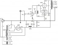
Here's an example of a 300B Monkey that I built for a friend using Magnequest power transformer and FS-030:
I guess what I am driving at is that this is a great amp for an audio experimenter able to compute component values and to juggle them to achieve the desired results in an optimized circuit. If you can find the exact power supply, plate choke, and tubes used in any particular schematic, then you have a reasonable chance of the amp operating to the drawing. But in general, this is not the type of circuit that you can build from a schematic and expect it to operate properly simply because there are too many variables that need to be determined as the build progresses.
Here's an example of a 300B Monkey that I built for a friend using Magnequest power transformer and FS-030:
Attachments
Thanks. I'm working may through this, but need something other than a bare picture (a la Welborne DRD) to get ideas.
I have the welborne schematic with values and spice simulation if you want it.can't post it before Sunday
 Please do not post copyrighted material here, redraw the schematic and post that instead.
You're looking for ideas? I have a few in this thread: http://www.diyaudio.com/forums/tubes-valves/207968-300b-other-dht-biasing-options.html
If you're interested in the Loftin-White circuit, you can also dig out their original paper.
~Tom
If you're interested in the Loftin-White circuit, you can also dig out their original paper.
~Tom
Welborne Labs DRD 300B amp
FWIW, manuals to build old Welborne Labs tube amps including DRD 300B amp are available from Rob Welborne's web site (10 bucks each!). I had a pair of factory build DRD 300B amps for a while and they sounded sweet. I would use tube rectified version.
FWIW, manuals to build old Welborne Labs tube amps including DRD 300B amp are available from Rob Welborne's web site (10 bucks each!). I had a pair of factory build DRD 300B amps for a while and they sounded sweet. I would use tube rectified version.
So I have a question here... The cap on the output stage will see over 700 V during start-up (so basically until the 300B heats up and starts conducting). Isn't that a pretty severe flaw in this circuit?
I notice that Jack Eliano's original circuit has a 450 V cap in that spot. While that's fine during normal operation with 400ish V across the 300B, it's not fine during start-up.
Am I off base here? Does the 2.5k-ish resistance from the cap to ground prevent the cap from blowing up? Mind you that if the cap shorts out, the current will "only" be limited to 280 mA...
~Tom
I agree. A 450V electrolytic will certainly have its specifications violated in that design. And I have blown the lid off 400V 'lytics with 500V accidents. So I agree, 700V supply should have 700V worth of cap.
The designer of that circuit clearly believed that 1000uF in that position was important, and did not want to compromise with series connected parts. It's not a choice I would agree with.
If we preheat the 300B filament before the B+ arrives (which should always be done) and use a slow-start, slow ramp rectifier (6CJ3 etc - takes 30s to reach full dc output) we can decrease the stress on the cap. But even then, if the 300B filament breaks (frequent modern production DHT failure mode) - the cap gets 700V continuous.
The version of the design shown by Palustris gets this right, and is a better design in many ways. I would suggest using that for a starting point, rather than the original. In particular, using a low-voltage driver valve like 6N23, E88CC and the like (90V anode voltage operation) allows a main supply of <500V - much safer than 700V, and allows more reasonable cap choices.
The version of the design shown by Palustris gets this right, and is a better design in many ways. I would suggest using that for a starting point, rather than the original. In particular, using a low-voltage driver valve like 6N23, E88CC and the like (90V anode voltage operation) allows a main supply of <500V - much safer than 700V, and allows more reasonable cap choices.
I prefer running higher voltages across the 300B. 400 V, 90 mA works well with a 5k primary OPT. So the voltage adds up quickly. That's why Jack's design used a 700 V B+.
Reducing B+ to 500 V does make part selection easier, though.
Thanks for the reality check.
~Tom
Have you been able to complete the build? I am very curious about how this design sounds. Some have commented in the past that it is more detailed but perhaps a tad analytical. I have no idea. I have also been looking at the Axiom Amp which requires a good deal more iron. Sorry to ask such a subjective question but...what are you impressions?
So I have a question here... The cap on the output stage will see over 700 V during start-up (so basically until the 300B heats up and starts conducting). Isn't that a pretty severe flaw in this circuit?
I notice that Jack Eliano's original circuit has a 450 V cap in that spot. While that's fine during normal operation with 400ish V across the 300B, it's not fine during start-up.
Am I off base here? Does the 2.5k-ish resistance from the cap to ground prevent the cap from blowing up? Mind you that if the cap shorts out, the current will "only" be limited to 280 mA...
~Tom
IIRC, Welborne lab version used reduced plate voltage to avoid stressing the cap and tube itself. Output power was limited to 6.5-7 Watts.
IIRC, Welborne lab version used reduced plate voltage to avoid stressing the cap and tube itself. Output power was limited to 6.5-7 Watts.
There may have been cost and safety constraints more than reliability concerns. Over 50 amps were built in a class in San Francisco years ago. As far as I know, all are still functioning.
- Status
- Not open for further replies.
- Home
- Amplifiers
- Tubes / Valves
- Welborne 300B DRD amp