I bought a teensie IC-based kit from Weber...they call it a "vibrato" add-on kit for tube amps, in Fenderish vernacular but admit it's really just a "tremolo". They provide some installed circuit samples, but don't provide the matching 'before' circuit nor much explanation.
I've made some all-solid-state tremolos before, to put into an effects loop or as a pedal, with just a low-frequency oscillator and a voltage-controlled amplifier (or some kind of photo-resistor device etc.). But I'm kind of lost integrating this solid-state IC tremolo on a tube amp.
I assembled the components onto the board, but I confess I really don't understand what the heck I bought or how to integrate this IC board with a tube amp.
I haven't even decided which amp to install this little tremolo kit on, probably the hacked-up salvage Peavey Classic 50 which is coming along nicely and already has reverb. That way I would just put an effects loop on the Fender and use the valverb there to add reverb & tremolo if/when I want it on the Fender. Or I might put the tremolo on the little 5-watt Champ clone I just picked up.
Any and all help or advice appreciated.
They are assuming you have some basic knowledge of existing amps.
You pretty much need to decide what you want to install this in, and THEN we can discuss how to go about it. Posting those sample circuits woulod be helpful as well as the schematic for it.
AMps all tend to be very similar, details vary, but the basic form of the amps tend to follow certain patterns. Tremolos in old Fenders for example are usually either an optocoupler acting as a variable volume elemnent, or are somehow linked to the bias of the power tubes or other similar. Once we know if it is a bias shaker or an opto type amp, we then can interface your unit. And other methods exist beyond those two.
I want to install it in the Peavey Classic 50. Here's what Weber provides: https://taweber.powweb.com/store/vibe_schem.jpg any help is greatly appreciated.
Your Weber unit sends out the trem signal. The circuit to the right of that is a typical Fenderish amp circuit, the two inpout channels are separate, and mix together with the pair of 220k resistors. The trem will affect only channel 2 on the example, so you'd add the pot and switch, and wire the Weber to the pot wiper.
On the C50, the equivalent circuit would be the NEXT point on the schematic. C3, upper right of page 1, is the preamp output, it feeds into the phase inverter upper left of page 2. I'd adapt to that by adding a largish cap in series between the switch and the 220k resistor in their example. There is no 220k in the C50, so I would connect that cap to the NEXT point.
Alternatively, I could add a series resistor and another cap between C3 and the NEXT point. And then wire the thing up the same as their example, switch wired to my new resistor.
The example farther right is what I call a bias shaker. The trem LFO (low frequency oscillator) is wired to the bias supply, so it adds and subtracts voltage with each cycle, and that alters the tube bias cyclically, and thus modulates the tube gain. You could do that one also.
On the C50, right under the power tubes, see C10 and it says BIAS? That is your bias supply. On the Weber example, that is the wiper on the bias adjust trimmer. NOte the C50 has a pair of 220k grid return resistors with an arrow to BIAS at their junction. To put that in the C50, you would add the 250k pot. One end to the bias supply, and the other end to the output of the Weber unit. Then the wiper of the pot would connect to those two 220k resistors. You would break the original connection from bias supply directly to the resistors. R49,50, and C10 are all on the power tube board, right around V4. The traces might be a bit touchy to separate, so I might just lift the bias end of the two resistors, join them, and run a wire to the control.
Neither method is blindingly simple, but neither is overly tough either.
Excellent! Thanks; you are the greatest! All those methods sound interesting. I love the idea of modulating the bias, just to see what it sounds like!
So what modulated DC voltage range does this little add-on circuit put out? I'm amazed it comes with no specs at all.
So what modulated DC voltage range does this little add-on circuit put out? I'm amazed it comes with no specs at all.
I have no idea.
Wire power to it and find out.
Or put your tech questions together and ask the Weber folks.
Looking at its schematic, I see "one side of heaters" as the source of power. I'd guess with a center tap that would be 3vAC, and the doubler circuit then makes about 8vDC? Chip runs single supply, so 4v each direction for signal, and so maybe 3v of LFO?
Hard to say. You tell us.
Yes, you are pretty close, as always 😉
Unusual LM2905 was used there because it can run with as low as 3V, single supply, and is very happy with 5V found in typical Logic boards.
Its output can swing *almost* rail to rail, so , say, 7Vpp.
I think you have a somewhat rounded squarewave there, don't see the slightly more complex net needed for sinewave.
And it's designed for bias shifting tremolo, either straight in the power tube grids or into the phase inverter.
The Fet shown amplifies it to tens of volts.
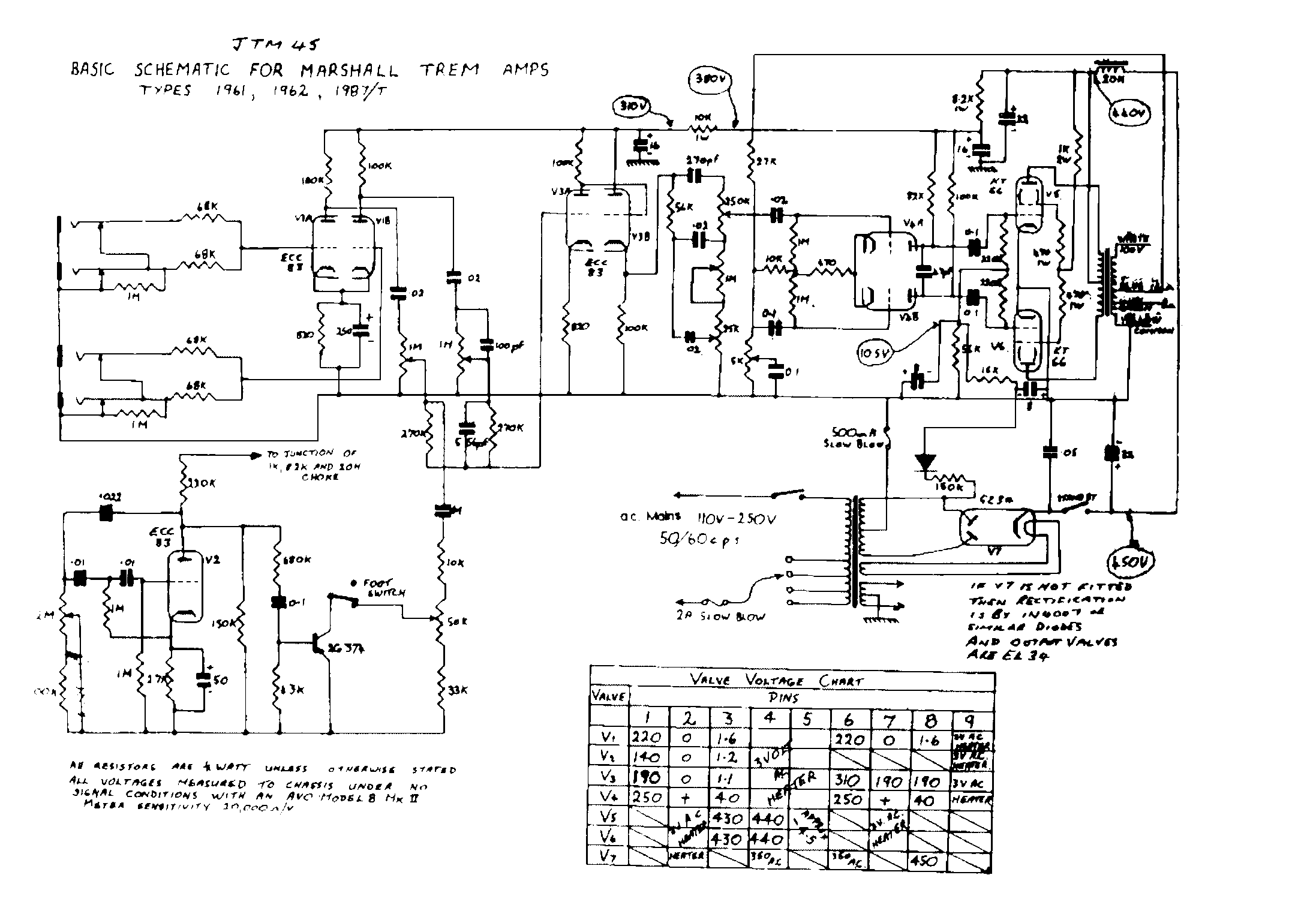
I'm sure the oscillator can modulate a FET or transistor for a variable resistance modulator, as in the JTM45T:
You'll have to modify the driving resistors because the around 3V RMS available here are much less than the 30 or 40V RMS available from a tube oscillator, of course.
As Enzo pointed, this is more a tool for creative modders than a "paint by the numbers" project.
EDIT: re-reading the OP, I think you can also drive a small NPN transistor, with , say, 22K to its base, and a Led/LDR Opto from its collector to +8V, with 220 or 470 ohms in series for safety, and wire the LDR similar to a classic Fender tremolo.
That would be the most "universal" option.
Unusual LM2905 was used there because it can run with as low as 3V, single supply, and is very happy with 5V found in typical Logic boards.
Its output can swing *almost* rail to rail, so , say, 7Vpp.
I think you have a somewhat rounded squarewave there, don't see the slightly more complex net needed for sinewave.
And it's designed for bias shifting tremolo, either straight in the power tube grids or into the phase inverter.
The Fet shown amplifies it to tens of volts.
I'm sure the oscillator can modulate a FET or transistor for a variable resistance modulator, as in the JTM45T:
You'll have to modify the driving resistors because the around 3V RMS available here are much less than the 30 or 40V RMS available from a tube oscillator, of course.
As Enzo pointed, this is more a tool for creative modders than a "paint by the numbers" project.
EDIT: re-reading the OP, I think you can also drive a small NPN transistor, with , say, 22K to its base, and a Led/LDR Opto from its collector to +8V, with 220 or 470 ohms in series for safety, and wire the LDR similar to a classic Fender tremolo.
That would be the most "universal" option.
Attachments
Last edited:
Thanks for all the details.
I certainly like the idea of using an optoisolator between a low-voltage solid-state oscillator and the high-voltage tube circuits. Then my task boils down to making a light blink at variable rates on one side, and wire a depth pot around the LDR on the other side. That's about as easy and safe as it gets. I'd like it before the master volume. I'll have to think about whether I'd want it before or after an effects loop...
45 years ago I built a solid-state Eico tremolo kit. The circuit board is still in the garage. But I don't think it used any opto-isolator, it was meant to work at guitar stomp-box levels and I think it just had a 1-transistor oscillator and a 1-transistor VCA. I remember driving the VCA with a bench signal generator instead, and the on/off/on/off of the square wave (very Pink Floyd) versus a very subtle effect of just a narrow but slightly rounded short duty-cycle upward-only spike, versus a triangle or sawtooth, or the slow build and subside of the sine. I think swell and decay of sine is very usable, but 100% depth on/off square has its uses as a special effect. Varying the duty cycle of the square wave is useful for Hendrix machine-gun effects or for harmonica. If you've ever seen Sugar Blue (of Chicago; played on some Stones recordings) he uses a tremolo stomp box running very fast and deep with harmonica, very useful when breath and tongue can't keep up. Analog synths really took the control of a VCA to extremes with a very flexible LFO. The most flexible is to get an old synth LFO, drive an optoisolator, and put it in its own box and plug it into the effects loop.
Now I've really got to decide what to do. Maybe I'll scrap the whole idea of putting it into the Peavey; the turret-construction Champ might be a lot easier to experiment with, and a much simpler host. No issues of master volume or effects loop.
Optos will certainly isolate circuits, but so does a cap. If you need level shifting, as in turning 3vAC into 30vAC, then you need that too, but if the little solid state unit puts out enough LFO voltage, then a DC blocking cap at its output effectively isolates it from the tube voltages.
- Status
- Not open for further replies.
- Home
- Live Sound
- Instruments and Amps
- Weber tremolo kit