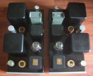
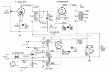
If you build it as drawn, try bypassing the 3K3 resistor on the grid of the 300B wiht a clip lead and see how the sound changes. It is not needed for proper circuit operation.
dave
dave
dave slagle said:If you build it as drawn, try bypassing the 3K3 resistor on the grid of the 300B wiht a clip lead and see how the sound changes. It is not needed for proper circuit operation.
dave
I generally use 1K resistors here, and that is as assurance against VHF oscillations which do occasionally occur even with 300B dht depending on layout. The noise contribution of that resistor is miniscule in relation to the signal levels present at that point.
Of more concern is the fact that the 417A needs to be handled very carefully when swinging these kinds of plate voltages as you will be swinging the grid over more or less its entire linear operating range and then some. I would use a 1:2 or 1:2.25 step up here - say 10K:40K/50K or similar. (Note that the driving source Z seen by the 300B with the proposed changes will be less than 10K with 1:2, less than 12K with 1:2.25 so HF BW will be ok.)
I have designed and built choke loaded 417A/5842 to drive 71A - works really well, and sounds great. I've no doubt with the right IT you will achieve excellent results. I run the 417A at 15 - 20mA with 150V on the plate. (Approximately -1 to -1.2V fixed bias on the grid, varies a lot due to variations in GM from tube to tube.)
The 100V rating of the cathode bypass cap seems a little marginal to me, especially if you're choosing an electrolytic. Lower ESR is obtained with higher voltage rated caps (which is easy to find in 220 uF).
Does anyone know what happened to Thomas of Diyaudio.hk (tube-lover)? He ripped me off to the tune of $800 on eBay for one of his amplifier kits.
John
John
Here's the SJS 417A/437A version of the amp.
An externally hosted image should be here but it was not working when we last tested it.
jlsem said:Does anyone know what happened to Thomas of Diyaudio.hk (tube-lover)? He ripped me off to the tune of $800 on eBay for one of his amplifier kits.
John
Last time I knew anything unfortunately he was fighting a severe form of cancer. He has not been active here for quite a few months so it is possible he did not win that battle. His last post here was May 8th.
Have you contacted eBay about this, and when did you bid on this amplifier kit?
By an impossible coincidence, the amplifier I bought from him arrived this morning. Before anyone chastises my rush to judgement, let it be known that I bought this kit in December 2007 and haven't heard from Thomas since July. So, after ten months of patience, politeness, and consideration of his medical condition, I am forced to eat crow on a public forum. It's the story of my life. Thomas, if you are still with us, I want to offer my apologies.
John
John
I always find it funny when people use an IT and go with cathode bias on a 300B.... Especially when we're only talking 150v across the primary.
Having prototyped a 300B design recently with WE300B tubes, I've concluded that I'd rather use an interstage transformer for driving the 300B grid. As you start to approach zero volts the 300B becomes quite a load and linearity suffers with typical RC coupled designs.
What I find interesting in that many designs which use an interstage driver transformer provide no load on the driver (interstage driver secondary) beyond the 300B tube itself. Considering transformers reflect impedance from the secondary to the primary it would appear many designs are running without any load until you get to the upper limits of driving the grid, which is incorrect.
Regards, KM
kmaier said:...many designs are running without any load until you get to the upper limits of driving the grid, which is incorrect.
Regards, KM
Could you elaborate? The concern seems to be the transition from unloaded to loaded, what in particular using an IT?
I was hoping someone could explain the purpose of B- on this schematic ?
Sort of going over my head at the moment ...
Sort of going over my head at the moment ...
korneluk said:Here's the SJS 417A/437A version of the amp.
An externally hosted image should be here but it was not working when we last tested it.
audiowize said:I always find it funny when people use an IT and go with cathode bias on a 300B.... Especially when we're only talking 150v across the primary.
which schematic are you refering to?
rdf said:
Could you elaborate? The concern seems to be the transition from unloaded to loaded, what in particular using an IT?
Well, if you look at the schematic (SJS amp) posted above, the secondary of the interstage transformer has no load. In theory, when a grid is negative it provides no load until it becomes positive, at which point it draws power. The 300B effectively provides little to no load until you start approaching zero on the grid, then it starts to create a load, before going positive.
Point being that the interstage transformer matches the load to the driver tube in the same manner as the output transformer matches the speaker (load) to the output tube. In this particular scenario, the driver tube sees little to no load for most of it's dynamic range. In my humble view, this is in incorrect.
Regards, KM
- Status
- Not open for further replies.
- Home
- Amplifiers
- Tubes / Valves
- We417+300b


