this is a better one.
tested already.
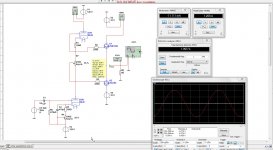
I did drawn a fast amp so like yours, but did dc couple the mosfets like I always did with my amp here who plays now for already 7 years.
It is afcourse simple, decoupling and such you have to do yourselfs, this can sound nice, little high distortion most second harmonics..
R4 is offset and R7 current mosfets.
Just a idea.
Attachments
Last edited:
Thanks, but I am looking for some infos about the MJ amp!
Why?this is a better one.
Cassiel wrote it in the tube amps forum:
This is why I am trying to get info here..., but still no luck....No, sorry, only the schematic. Got it from the Solid State forum, maybe if you ask there....
It seems that nobody is interested in this topic...
One question:
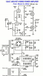
Why is the complementary buffer stage connected to the + and - 120Vdc of the SRPP tube section??
One question:
Why is the complementary buffer stage connected to the + and - 120Vdc of the SRPP tube section??
Built this amp some ten years ago,(the DC coupled version) worked perfectly for many years, very-very good sound from this one... One thing to pay serious attention, is the powerup sequence, if you turn it on like on the schematic, you will have huge DC swing (and possibly destruction of the FET-s) while the tube heats up. One thing you can do (what I did) is insert a relay beetween the tube output (the two ends of,R7) and the gates of the FET-s with an approx. 40-60 sec delay. Also using Zener protection diodes on the gates is a good idea. What other info you are looking for?
Thanks, but I need info about the MJ amp. The first one.
Why is the complementary buffer stage connected to the + and - 120Vdc of the SRPP tube section??
Why is the complementary buffer stage connected to the + and - 120Vdc of the SRPP tube section??
As you see on the original (MJ) schematic, it is a voltage divider composed by the resistor chain between the + and the - 120V rails of the tube stage power supply. These elements provide the necessary Ugs bias voltages (approx +/- 1.3 Volts) for the output Fet-s. The middle point - the common leg of the two360 ohm resistors- should be at 0 volt (you can adjust it with the 5k trimpot on the neg. side). To change Io of the Fet-s, you can alter the values of the 360 ohm resistors (more resistance - higher Io). With the given values the idle current is around 0.5-0.6 A - see the diagram
Attachments
Built this amp some ten years ago,(the DC coupled version) worked perfectly for many years, very-very good sound from this one... One thing to pay serious attention, is the powerup sequence, if you turn it on like on the schematic, you will have huge DC swing (and possibly destruction of the FET-s) while the tube heats up. One thing you can do (what I did) is insert a relay beetween the tube output (the two ends of,R7) and the gates of the FET-s with an approx. 40-60 sec delay. Also using Zener protection diodes on the gates is a good idea. What other info you are looking for?
I have build one with a mosfet CCS on one side and a tube on the other, you see afcourse yourself that when switch on the mosfets get the full 120 volts on the gates, I have still this amps and never did blow a fet.
Now i have a double triode and no mosfet CCs anymore, now the voltage stays low in the middle where the mosfets are connected, still need a protection.
when a tube gets defect it can blow the fets, I have diodes for this protection inserted.
To have positive and negative bias voltage for the output mosfets.
No need for symetric supply for the SRPP it has a capacitor and the bias for the mosfets can also be taken from the plus and min 33 volts.
What i did drawn need a symetrical supply because it is dc connected.
To have positive and negative bias voltage for the output mosfets.
Thanks, I know it. I meant why is this made from the tube sections 120 Voltage rails? Why not from the buffer's own suplly rails??As you see on the original (MJ) schematic, it is a voltage divider composed by the resistor chain between the + and the - 120V rails of the tube stage power supply. These elements provide the necessary Ugs bias voltages (approx +/- 1.3 Volts) for the output Fet-s.
I did drawn a fast amp so like yours, but did dc couple the mosfets like I always did with my amp here who plays now for already 7 years.
It is afcourse simple, decoupling and such you have to do yourselfs, this can sound nice, little high distortion most second harmonics..
R4 is offset and R7 current mosfets.
Just a idea.
Th9s idea unfortunately shows the differences between a simulation and the real worls. In a simulation it works, but in the real world you would have some big problems.
First, there is a fundamental error in the circuit which has to do with the biassing of the bottom triode. This has it's cathode desoupled to -120V, which is INCORRECT. Keep in mind that the cathode must be AC referenced to the same reference as the input signal, and this is ground, not -120V. A REAL rather than simulated 120V supply will have hum, ripple and noise and the bottom triode as drawn, will gladly amplify it because it's cathode has been decoupled, and thus AC-referenced to the -120V supply. Since the input is referenced to ground, and the actual input to the circuit is the AC component of Vak, this becomes Vin + Vripple. In this situation the input AC to the triode is actually the input signal plus (120V supply ripple, noise and hum) in series.
The correct way to do this is to decouple the cathode to ground, not -120V.
Second, in the real world triodes are not the same nor do they remain constant long-term (and while heating up not even close to constant short term). Because of this there will be potentially very large offset voltages on the output of the circuit, generated by differences in the operation of the triodes while the circuit is heating up, and then as it ages. A speaker protection with delay is needed, at the very least the gates of the MOSFETs can be clamped to GND initially with a small relay, operating from a delay circuit. However, this does not solve the problem of aging, so the balance trimmer would need to be readjusted periodically. In most cases using lateral MOSFETs dispenses with the requirement to use gate protection diodes as these are built into the MOSFETs, but one needs to chose appropriate gate resistors. Adding a 1meg or so resistor to ground from at least one fot he gates will protect from the case where there is no tube plugged into the socket, as in the circuit as it stands now, this case leaves the gates floating, so a buildup of static sould cause one MOSFET to conduct sufficiently to blow a speaker on the output.
There are a number of things that can be done to stabilize the circuit and offer some other advantages. A combination of CCS and DC servo could easily dispense with all offset adjustments, and only the bias of the output stage need be adjusted. The bottom triode gets a CCS in it's cathode, and the cathode is decoupled to GND. The top triode has it's gate fed from a simple DC cervo (single op-amp integrator) via a large resistor (say 470k), and the gate is not connected to the bottom of it's cathode resistor directly, but rather via a small coupling cap (the 470k resistor to the output of the DC servo makes it possible to use a small value, say 0.1-0.22uF). The DC servo time constant must be quite low, so that the bottom triode cathode coupling to GND and the top triode grid coupling have a higher time constant - say 10x, to prevent servo 'pumping'. For AC this results in a completely equivalent circuit, but now the tube part currents are fixed by the CCS and the balance adjustment is done automatically by the DC servo. As a bonus, because of the CCS in the bottom triode cathode, the power supply hum rejection for the -120V power supply is very high. A reshuffling of the bias pot and cathode resistor for the top triode might offer a lowr output impedance from the tube part of the circuit and a variant may even make a true mu-stage with higher gain - in any case working to lower the output impedance of the tube stage is beneficial to driving MOSFETs due to their fairly large and, more importantly, quite nonlienar input capacitance - the combo of tube stage output impedance and nonlinear MOSFET input capacitance generates a nonlinear amplitude variable high-pass filter which may produce more high order harmonics than expected by intermodulation - most simulator MOSFET models do not model non-linear capacitances so this will not be evident in a simulation. However, this bit of refinement I will leave to you to figure out 🙂
The one remaining problem with this circuit is a fairly high output impedance, which may not be liked by some speakers. Unfortunately any path to lower output impedance leads to either increasing the capacitance the tube stage has to drive (bigger or more MOSFETs in parallel), must introduce some form of NFB (for which there is really very little extra gain!), or increases the amount of heat due to a higher required bias current - MOSFET gm increases with bias current, and output impedance is roughly 1/gm so this decreases for higher bias currents - but the distortion character changes, or requires a completely different and more complicated output stage.
IMHO the best virtue of this circuit is it's simplicity (which does not mean one should not add a bit of complication and sophistication to manage the operating points of the tubes 🙂 ), so I think the best bet would be keeping it simple and choosing the right speakers, ones suitable for tube amps will do well, the key is that they should have fairly constant impedance WRT frequency.
Last edited:
Th9s idea unfortunately shows the differences between a simulation and the real worls. In a simulation it works, but in the real world you would have some big problems.
First, there is a fundamental error in the circuit which has to do with the biassing of the bottom triode. This has it's cathode desoupled to -120V, which is INCORRECT. Keep in mind that the cathode must be AC referenced to the same reference as the input signal, and this is ground, not -120V. A REAL rather than simulated 120V supply will have hum, ripple and noise and the bottom triode as drawn, will gladly amplify it because it's cathode has been decoupled, and thus AC-referenced to the -120V supply. Since the input is referenced to ground, and the actual input to the circuit is the AC component of Vak, this becomes Vin + Vripple. In this situation the input AC to the triode is actually the input signal plus (120V supply ripple, noise and hum) in series.
The correct way to do this is to decouple the cathode to ground, not -120V.
Second, in the real world triodes are not the same nor do they remain constant long-term (and while heating up not even close to constant short term). Because of this there will be potentially very large offset voltages on the output of the circuit, generated by differences in the operation of the triodes while the circuit is heating up, and then as it ages. A speaker protection with delay is needed, at the very least the gates of the MOSFETs can be clamped to GND initially with a small relay, operating from a delay circuit. However, this does not solve the problem of aging, so the balance trimmer would need to be readjusted periodically. In most cases using lateral MOSFETs dispenses with the requirement to use gate protection diodes as these are built into the MOSFETs, but one needs to chose appropriate gate resistors. Adding a 1meg or so resistor to ground from at least one fot he gates will protect from the case where there is no tube plugged into the socket, as in the circuit as it stands now, this case leaves the gates floating, so a buildup of static sould cause one MOSFET to conduct sufficiently to blow a speaker on the output.
There are a number of things that can be done to stabilize the circuit and offer some other advantages. A combination of CCS and DC servo could easily dispense with all offset adjustments, and only the bias of the output stage need be adjusted. The bottom triode gets a CCS in it's cathode, and the cathode is decoupled to GND. The top triode has it's gate fed from a simple DC cervo (single op-amp integrator) via a large resistor (say 470k), and the gate is not connected to the bottom of it's cathode resistor directly, but rather via a small coupling cap (the 470k resistor to the output of the DC servo makes it possible to use a small value, say 0.1-0.22uF). The DC servo time constant must be quite low, so that the bottom triode cathode coupling to GND and the top triode grid coupling have a higher time constant - say 10x, to prevent servo 'pumping'. For AC this results in a completely equivalent circuit, but now the tube part currents are fixed by the CCS and the balance adjustment is done automatically by the DC servo. As a bonus, because of the CCS in the bottom triode cathode, the power supply hum rejection for the -120V power supply is very high. A reshuffling of the bias pot and cathode resistor for the top triode might offer a lowr output impedance from the tube part of the circuit and a variant may even make a true mu-stage with higher gain - in any case working to lower the output impedance of the tube stage is beneficial to driving MOSFETs due to their fairly large and, more importantly, quite nonlienar input capacitance - the combo of tube stage output impedance and nonlinear MOSFET input capacitance generates a nonlinear amplitude variable high-pass filter which may produce more high order harmonics than expected by intermodulation - most simulator MOSFET models do not model non-linear capacitances so this will not be evident in a simulation. However, this bit of refinement I will leave to you to figure out 🙂
The one remaining problem with this circuit is a fairly high output impedance, which may not be liked by some speakers. Unfortunately any path to lower output impedance leads to either increasing the capacitance the tube stage has to drive (bigger or more MOSFETs in parallel), must introduce some form of NFB (for which there is really very little extra gain!), or increases the amount of heat due to a higher required bias current - MOSFET gm increases with bias current, and output impedance is roughly 1/gm so this decreases for higher bias currents - but the distortion character changes, or requires a completely different and more complicated output stage.
IMHO the best virtue of this circuit is it's simplicity (which does not mean one should not add a bit of complication and sophistication to manage the operating points of the tubes 🙂 ), so I think the best bet would be keeping it simple and choosing the right speakers, ones suitable for tube amps will do well, the key is that they should have fairly constant impedance WRT frequency.
Hi
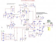
I have this design now working for 5 years and never a problem, but yes here the driver has a gate resistor to ground, my drawn here was a example fast made, and so also errors, tube part U1B was first a mosfet CCS so always there was min 120 volt on the gates when switch on, I have never blow a fet in al these years (and i did pust it to limits), now I have a double tube who do replace that ccs, I have a servo included, that is also a age tracker for the tube, I have a slow switch on who do protect the speakers when dc on start daleying 90 seconds when switch on.
the drawn here was a quick one, simulations is however really accurate i did discover with my own design.
But you give a nice learningfull answer for the people here.
thansk
Attachments
Last edited:
- Status
- Not open for further replies.
- Home
- Amplifiers
- Solid State
- Wanted! 12AU7-Mosfet hybrid from Musen to Jikken