Guys,
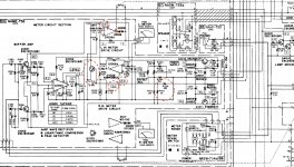
I really like the way the Onkyo meters work. Fast and sharp response. These meters are the best that I ever seen so far. This is why I decided to build circuit based on this design. Obviously is not only the circuit to ensure this performance but also the meters! I hope you can help me determining the proper meters available on the market. I have TA7318 so I'll try to build similar circuit. (Original schematic attached)
First I am trying to understand how the circuit works and I have coupe of questions that I hope you guys can help me.
1. MJM4558. on the schematic it shows they are running at +21V/-21V.
Why? the data sheet says maximum voltage is +/-18V.
2. Diodes, D1006 & D1008. they are used here to prevent deflection of the
meters after power up. They are then bypassed by the relay that is driven
by the protection circuit. D1006 is 15V zener. Based on the 21V supply at t
the output of the Q1006 the voltage is above zener where the diode starts
conducting so the meter deflection must occur.
3. Q1005, what is the purpose of this transistor? It seems to be
protection from meter moving when the speakers are still off. I don't
understand, the base is driven by the lamp driver. The lamp driver is
driven by the same protection circuit that also drives the relay to bypass
the diodes mentioned above.
To turn of the transistor the base is driven negative -3.6V. which is
impossible it rather be - 0.6V. How could the measure -3.6. I know the
resistors R1047 & R1048 make a voltage divider and will give -3.6V but
only if the transistor is not there. Besides the collector when the protection
circuit is hight so supposingly it should fully turn on the transistor but it
remains floating so the signal will flow from the Q1003 anyway and not
protecting the meter from moving...
Attachments
Meter sensitivity
Has anyone know the sensitivity of the Onkyo meters used in integra M-5060, M-506, 506, 508 etc? I know the DC resistance 690 Ohms.
Has anyone know the sensitivity of the Onkyo meters used in integra M-5060, M-506, 506, 508 etc? I know the DC resistance 690 Ohms.
No idea but it is easy to measure with a preset and a battery and a DVM. Just set the preset to give FSD and either have the DVM measuring current to the meter or use ise it to calculate current from the drop across the preset resistance (which you would measure).
Takes as long to do as to type this 😉
Takes as long to do as to type this 😉
> Q1005 Q1004 left channel
> the base is driven negative -3.6V. which is impossible it rather be - 0.6V.
No. It is NPN, grounded emitter. The base can be driven to +0.7V (saturation) or down to about -7V before breakdown. Anything under about 0.5V is "off"; -3.6V is for-sure-OFF but in no danger of breakdown.
Much of Onkyo's build may be hard to duplicate today. Try to get the TA7318P chip and play with it on breadboard.
No idea but it is easy to measure with a preset and a battery and a DVM. Just set the preset to give FSD and either have the DVM measuring current to the meter or use ise it to calculate current from the drop across the preset resistance (which you would measure).
Takes as long to do as to type this 😉
I know, but the problem is I don't have this meter. I was hoping someone might have this information.
I actually built similar circuit already. this voltage -0.6 i've measured. it is upsetting meter offset. I mean i can still adjust 0 offset but this is different to if the transistor was not there.
My quick thoughts on post #1
1/ Perhaps the devices are selected or an in-house part and rated for the higher supply. -/+21 isn't needed for such a circuit and it could easily be changed to use much lower voltages.
2/ The Zener will be a unique solution to the problem and will rely on the circuit producing a known offset at power on. In other words all circuits built using the production design should behave correctly. It is a neat engineering solution.
3/ As PRR says... an NPN B-E junction can be reverse biased up to around 7 volts at which point it conducts and becomes a (very) noisy Zener type junction. Many were used in this mode as wideband noise generators. The circuit is just the same as a transistor audio mute on a signal line.
4/
https://www.diyaudio.com/forums/solid-state/350930-onkyo-508-meter-circuit.htmlMy quick thoughts on post #1
1/ Perhaps the devices are selected or an in-house part and rated for the higher supply. -/+21 isn't needed for such a circuit and it could easily be changed to use much lower voltages.
Onkyo uses this design on almost all meters driver from that era.
2/ The Zener will be a unique solution to the problem and will rely on the circuit producing a known offset at power on. In other words all circuits built using the production design should behave correctly. It is a neat engineering solution.
TA7318, if uses single power supply deflects meters after power up. For high quality amp it is good idea to stop it by blocking the output of the opam for few seconds. I already built similar circuit powered from +/-15V and it does the job. I tried higher voltage and if it is above zener this protection doesn't work like that. it deflects the meter. Why onkyo would do that? Does it mean that they made errors on the schematic on purpose? Interesting is that these voltages were confirmed in one of the previous post Onkyo M-508 Meter circuiL]t problems[/UR
3/ As PRR says... an NPN B-E junction can be reverse biased up to around 7 volts at which point it conducts and becomes a (very) noisy Zener type junction. Many were used in this mode as wideband noise generators. The circuit is just the same as a transistor audio mute on a signal line.
I thought it is the muting circuit but it doesn't work in my circuit. So when the relay didn't open the contacts after power up to prevent meter deflection the signal from TA7318 moves the meter.
4/
The mute will not stop transients in the circuitry beyond that point from causing deflection at power up and power down. It is purely to mute the audio to the meter circuit.
I've never used or studied the TA7318 chip 🙂
I've never used or studied the TA7318 chip 🙂
On VU meter citcuits generally, the meter response speed is specified to be slow, in line with broadcast industry standards that require this for making sense of flickering needle movements, ease of reading and consistency from one operator to another. Here's the easy version: VU meter - Wikipedia)
Whether it's passive, discrete or IC circuitry, the speed of meter response is essentially determined by a big capacitor placed across the meter's DC drive circuit - the more capacitance, the slower the needle moves and the reading becomes more of an average level over a short (mS) period. The alternative you are looking for, is probably a type known as a peak reading VU meter and these were a switched option on up-market tape recorder control panels, back in 1970s-90s. It's not much use for level control but a peak response sure gives meter needle suspensions a work-out. Use a good quality meter or a very small one if you want it to survive in daily use.
The following link is to an interesting DIY article that outlines design criteria based on a practical VU meter project using common bits and pieces: https://www.audiotechnology.com/PDF/TUTORIALS/AT51_DIY_VU.pdf There also a good VU meter article and similar project by Rod Elliott at the ESP site: VU And PPM Audio Metering.
BTW, the standard panel meter for VU meters has a nominal 200uA sensitivity which is little different to most cheap panel meters fitted to Japanese audio gear since time began. I'd wager that the meters in Onkyo products also had such standard industry components, regardless of what meter drive circuits were used.
Presently, Chinese VU scaled meters vary between 100 and 500uA sensitivity but if you don't have any meters anyway, you'll need to buy some and the types you can buy will likely be accommodated in your circuit set-up adjustments (assuming you have or plan to build a circuit that has adjustable sensitivity).
Presently, Chinese VU scaled meters vary between 100 and 500uA sensitivity but if you don't have any meters anyway, you'll need to buy some and the types you can buy will likely be accommodated in your circuit set-up adjustments (assuming you have or plan to build a circuit that has adjustable sensitivity).
Last edited:
thanks Ian,
i tried Sifam AL39W VU meter but with very high impedance 2k I didn't like it at all. then I tried FR39W 450R 1mA, fast response. It is much better but still not even close to the Onkyo meters. I also have Chinese little one 500uA 650R which is the best at the moment but it is very small. It seems 200uA will be good choice. I have order 2 more for tests.
i tried Sifam AL39W VU meter but with very high impedance 2k I didn't like it at all. then I tried FR39W 450R 1mA, fast response. It is much better but still not even close to the Onkyo meters. I also have Chinese little one 500uA 650R which is the best at the moment but it is very small. It seems 200uA will be good choice. I have order 2 more for tests.
Note that the meter drive circuit is what determines the sensitivity and needle velocity of the actual meter, which is usually only specified with the DC current required for FSD. If your meter drive circuit doesn't have the oomph by dint of having too high an impedance or not enough current available at full scale, then no meter can be expected to compensate for it. I think you'll find that any or all of your meters could actually be used to get a fast response but the drive current capability has be sufficient to allow it. As suggested earlier, some meter models also contain the caps that slow the response speed so check this with a simple battery/resistor test circuit and/or visual inspection.
With opamp circuits, simply changing the type to say, an NE5532, could allow sufficiently increased drive current. For a discrete circuit, you may need more current gain from your DC output transistor(s) to get the speed.
With opamp circuits, simply changing the type to say, an NE5532, could allow sufficiently increased drive current. For a discrete circuit, you may need more current gain from your DC output transistor(s) to get the speed.
Meter electric sensitivity can be matched with driver design. I have seen 100 milliAmp meter with a monster driver.
Meter movement *speed* has the same influences as a loudspeaker. Moving mass, electromagnetic coupling. Like a speaker, loud and fast costs more. There is marginal improvement possible with a "speed-up" in the electric path, but this has to be hand-tweaked (we can't know the constants of some random movement).
If you love the dynamics of Onkyo meters Integra M-???? maybe you should collect "for parts" amplifiers from the auction sites?
[If you love the dynamics of Onkyo meters Integra M-???? maybe you should collect "for parts" amplifiers from the auction sites?][/QUOTE]
I would consider this if the prices are reasonable... do you know where to look? I tried eBay but is nothing there.
I would consider this if the prices are reasonable... do you know where to look? I tried eBay but is nothing there.
Note that the meter drive circuit is what determines the sensitivity and needle velocity of the actual meter, which is usually only specified with the DC current required for FSD. If your meter drive circuit doesn't have the oomph by dint of having too high an impedance or not enough current available at full scale, then no meter can be expected to compensate for it. I think you'll find that any or all of your meters could actually be used to get a fast response but the drive current capability has be sufficient to allow it. As suggested earlier, some meter models also contain the caps that slow the response speed so check this with a simple battery/resistor test circuit and/or visual inspection.
With opamp circuits, simply changing the type to say, an NE5532, could allow sufficiently increased drive current. For a discrete circuit, you may need more current gain from your DC output transistor(s) to get the speed.
I have modified my circuit to be able to calibrate the meters. Both meters run at the same settings, one is 1mA 450R and the second 500uA 650R.they are calibrated to FSD but I can tell the 500uA is faster and it is close to "ONKYO". Needle response is almost to every bit. Looking at the 500uA needle you can feel the rhythm not like it the other one where it seems to loose it "as a bad dancer". It seems that the driving circuit must be very low impedance to have a good control over the meter or the meter must be very sensitive...
I'll try 130uA 650R when it arrive to compare.
- Home
- Amplifiers
- Solid State
- VU (PPM) Meter ONKYO M-5060