Hi All,
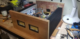
I am building a Hiraga Class A 30w, almost completed except for the addition of 2xVU meters. The meters and circuit are from JLM audio
JLM Audio Shop
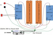
The Hiraga wiring is as per picture attached.
The VU meter requires 12V to run the circuit & LED and I was using the +35V rail of the Hiraga with a DC-DC buck converter to reduce to 12V, works fine. The VU meter has 3 additional inputs, +Vin, -Vin, +0V. I wired the Hiraga inputs to the VU meters and connected 0V to 0V on the CRC supply. The issue I am seeing is that the DC offset ant the outputs is effected enormously bt the addition of the VU meters and never seems to stabilise (keeps rising) before I decide to shutdown to avoid any potential damage.
So, my beginner question is how do I wire in the VU meters ? At the imputs (if so why is the offset all ove the place) or at the outputs (if so how??).
Any help greatly appreciated as always. Soooo clode to finisheing the amp....
Cheers
Richard
I am building a Hiraga Class A 30w, almost completed except for the addition of 2xVU meters. The meters and circuit are from JLM audio
JLM Audio Shop
The Hiraga wiring is as per picture attached.
The VU meter requires 12V to run the circuit & LED and I was using the +35V rail of the Hiraga with a DC-DC buck converter to reduce to 12V, works fine. The VU meter has 3 additional inputs, +Vin, -Vin, +0V. I wired the Hiraga inputs to the VU meters and connected 0V to 0V on the CRC supply. The issue I am seeing is that the DC offset ant the outputs is effected enormously bt the addition of the VU meters and never seems to stabilise (keeps rising) before I decide to shutdown to avoid any potential damage.
So, my beginner question is how do I wire in the VU meters ? At the imputs (if so why is the offset all ove the place) or at the outputs (if so how??).
Any help greatly appreciated as always. Soooo clode to finisheing the amp....
Cheers
Richard
Attachments
Use a linear 12 V supply. or a series resistor, the DC to DC converter is a problem.
See the schematics of old amps, you can connect at power amp input or output stages.
If you have DC offset issues, connect the other way from the currently connected wiring (reverse the tap off from input to output, or vice versa), see what happens.
See the schematics of old amps, you can connect at power amp input or output stages.
If you have DC offset issues, connect the other way from the currently connected wiring (reverse the tap off from input to output, or vice versa), see what happens.
Last edited:
A diagram of the VU circuitry would be helpful. If it needs only a single 12 volt supply then simple linear regulator is the best solution (imo) for such a low current requirement. If the current is really low then a simple resistor and Zener would suffice.
As to the other and the three addition inputs... no idea without seeing a diagram.
As to the other and the three addition inputs... no idea without seeing a diagram.
Schematic in link
VU BUFFER & PEAK LED KIT BUILD THREAD - JLM AUDIO
Dc converter
Adjustable Switching Power Supply Module IN 4V-35V OUT 1.5V-30V LM2596S Step-Down Converter Australia
So just a lm7812 oR similar would be preferred ?
Cheers
VU BUFFER & PEAK LED KIT BUILD THREAD - JLM AUDIO
Dc converter
Adjustable Switching Power Supply Module IN 4V-35V OUT 1.5V-30V LM2596S Step-Down Converter Australia
So just a lm7812 oR similar would be preferred ?
Cheers
So looking at the diagram...
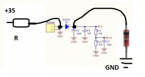
It uses so little current that a Zener supply is a good option. +35 volt rail less 12 volts is 23 volts to loose across the resistor. Lets say we allow 15 milliamps total. That gives a series R of around 1k5.
The Zener is connected across C6. The TL072 opamp only uses around 5 milliamps. A7812 is overkill. Keep it simple.
You feed the audio (assuming normal unbalanced) into C1 and leave the other input floating.
Thanks
I am unsure what you mean by the zener “across” C6, could you provide a sketch ?
Also, there is only one audio input on the buffer (V+ red and V- black) from the RCA input. Are you indicating not connecting one of these ?
Thanks again
I am unsure what you mean by the zener “across” C6, could you provide a sketch ?
Also, there is only one audio input on the buffer (V+ red and V- black) from the RCA input. Are you indicating not connecting one of these ?
Thanks again
Like this for the Zener. It is soldered anywhere on the board that places it across the supply.
An unbalanced (normal RCA input) should just use pins 2 and 3 on the diagram. Leave pin 1 of the BAL IN socket floating.
It is easy to alter the gain of the circuit if needed, just get it all working first.
The Zener supply of 12 volts as described is just for the board and meter movement. It will not supply filament bulbs for meter illumination as they would draw more current. If you want to use filament bulbs off the 35 volt supply then they are fed separately and would need a resistor value calculating based on current draw.
Attachments
Thanks so much. Thats the clearest instructions I have had. I will wire as you suggest and report back.
Cheers
Cheers
Ok, all working now. I found a dead tantalum on one VU buffer board and after desoldeing the other board and re-soldering/cleaning I have it working. No idea what the issue was. I wired as suggested above but had to connect the other balanced input to 0V for the meters to work. Leaving it floating showed no movement on the meters.
Thanks all
Thanks all
 that's good. Thanks for the update.
- Home
- Amplifiers
- Solid State
- VU Meter wiring question