I have been working on upgrading my TEAC VRDS-8, trying to come closer to the presence and ambience of my analog system.
So far I have installed a clock upgrade, changed I/V and filter/output opamps to OPA627s, and changed all the decoupling/filter caps to BlacK gates.
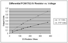
The VRDS-8 uses dual PCM1702 DAC chips per channel. From the schematic of one channel (should be attached) it looks like I could get a balanced signal output at the output of the I/V stages (two per channel).
I like the idea of keeping things simple, less components in the signal path, and I know how good transformers can sound from my S&B TVC, so I was thinking of some kind of transformer connected right at the I/V opamp outputs (is the opa627 the best in this application), driving a balanced output.. this would also provide filtering...
Or maybe I could go for a simple circuit with discreet components...
Or.. any other simple suggestions? I know there have been many threads around this topic but they seem to deviate off topic and they probably go way back in time.
So what is the current thinking / experience?
So far I have installed a clock upgrade, changed I/V and filter/output opamps to OPA627s, and changed all the decoupling/filter caps to BlacK gates.
The VRDS-8 uses dual PCM1702 DAC chips per channel. From the schematic of one channel (should be attached) it looks like I could get a balanced signal output at the output of the I/V stages (two per channel).
I like the idea of keeping things simple, less components in the signal path, and I know how good transformers can sound from my S&B TVC, so I was thinking of some kind of transformer connected right at the I/V opamp outputs (is the opa627 the best in this application), driving a balanced output.. this would also provide filtering...
Or maybe I could go for a simple circuit with discreet components...
Or.. any other simple suggestions? I know there have been many threads around this topic but they seem to deviate off topic and they probably go way back in time.
So what is the current thinking / experience?
Attachments
If you have balanced dac outputs, look at the Pass D1-DAC output stage: http://www.passlabs.com/downloads/old product/d1_servm.pdf
Several guys here stated that Op-Amps are not the ideal choice as DAC output stages http://www.diyaudio.com/forums/showthread.php?postid=396844#post396844 and based on their explanations it makes sense, although I didn't have had the possibility to hear such a gear...
Not yet - I'll go and build one, but I have to sort out some other things before.
Another possibility is to build this: http://www.diyaudio.com/forums/showthread.php?s=&threadid=6121&perpage=15&pagenumber=1
But with diff outputs maybe you have to change quite a bit...
Cheers, Tino 🙂
I would not assume that because there are two dacs it automatically follows that they are in a balanced configuration. The labelling R and SHIFT R suggests that they are in a staggered configuration.
Since the outputs of both I/V opamps feed straight to the + and - inputs of the next opamp, I would have thought they could just as well drive a transformer and give a balanced output... or am I missing something?
Hasn't anyone done something like this?
Hasn't anyone done something like this?
GerryM said:Since the outputs of both I/V opamps feed straight to the + and - inputs of the next opamp, I would have thought they could just as well drive a transformer and give a balanced output... or am I missing something?
<snip>
Yes, if the output to the dacs is staggered. You would have to remove the stagger and invert the input to one dac.
Have you looked at the schematic?
I know its sideways (to fit the size limits) but if one DAC output was not inverted then nothing much would come out of the next opamp after the I/V stages since they seem to preserve polarity.
As far as 'staggered' goes, I fail to see the significance (a nice way of saying I dont understand but I dont believe it anyway until proved otherwise).
Could you explain what you mean?
Also for anyone else:
Now I have narrowed the transformer search to either a Sowter 9545 or Lundahl LL1694 transformer.
Has anyone got experience of these or other transformers used with DAC outputs?
GerryM said:Have you looked at the schematic?
I know its sideways (to fit the size limits) but if one DAC output was not inverted then nothing much would come out of the next opamp after the I/V stages since they seem to preserve polarity.
As far as 'staggered' goes, I fail to see the significance (a nice way of saying I dont understand but I dont believe it anyway until proved otherwise).
Could you explain what you mean?
<snip>
It is not about the input to the I/V stage. It is about the input to the dacs. That part of the schematic is not there so one has to speculate. Based on other VRDS schematics and reviews a staggered configuration seems more likely to me.
Re staggered configuration
http://www.diyaudio.com/forums/showthread.php?s=&threadid=37981&perpage=10&highlight=&pagenumber=4
You are most likely right that the DAC output is staggered. The input circuit to the DACs (too big to attach as one legible file on the BB) has an AD1893 sample rate converter, followed by an SM5843 digital filter, plus lots of inverters, serial to parallel shift registers, analog multiplexers...
There is a control on the CD player for 'DS point' which I think changes the effective oversampling rate.
Tomorrow I'll stick a dual trace scope on the outputs of the I/V converters and see what it looks like.
However, back at the schematic - even in the case that the DAC outputs are 'staggered' or whatever, since they go to the + and - inputs of one op amp after I/V conversion, couldnt I still just wire in a transformer instead?
GerryM said:You are most likely right that the DAC output is staggered. The input circuit to the DACs (too big to attach as one legible file on the BB) has an AD1893 sample rate converter, followed by an SM5843 digital filter, plus lots of inverters, serial to parallel shift registers, analog multiplexers...
There is a control on the CD player for 'DS point' which I think changes the effective oversampling rate.
Tomorrow I'll stick a dual trace scope on the outputs of the I/V converters and see what it looks like.
<snip>
Much like another of the VRDS range. You could look at the LE input of the '1702 and check the frequency of LE. You could also see if frequency of LE changes with the DS point setting. If the LE signal is not common to both dacs check their positions relative to each other.
Rfbrw,
Forgive me for banging on about this, but regardless of the dac shifting/inverting/whatever, what would be the problem to connect a transformer to the outputs of the two dacs in one channel? This is really the issue, since you brought it up.
My hope is that I can remove all the circuitry after the dacs. I would connect 390R resistors from the Ioutputs to ground, then connect a 1:4 transformer across the Ioutputs for one channel to give me a useable output voltage.
I could even try connecting the Iouts with one load resistor and connect the transformer across it.. (maybe a little bit more dodgy)
The main question is, what is so wrong with this approach as long as the original circuit (attached to Post#1) shows the outputs of two dacs driving one opamp?
I can't see any reason why a transformer should not work. The op-amp is working as a differential amplifier so you should be able to replace it with a transformer but you will not get any common mode cancellation as the two dacs are not converting simultaneously assuming the output is not balanced.
BTW you really should seek a wider range of views on this as I am not a fan of transformers in the signal path so I cannot claim any great expertise in this matter.
Another modified VRDS.
http://www.diyaudio.com/forums/showthread.php?s=&threadid=33246&highlight=
BTW you really should seek a wider range of views on this as I am not a fan of transformers in the signal path so I cannot claim any great expertise in this matter.
Another modified VRDS.
http://www.diyaudio.com/forums/showthread.php?s=&threadid=33246&highlight=
In fact I never described all the mods I have done. I have implemented all audiotuning vrds-25 mods to the vrds-8 including digital filter upgrade (SM5843 -> DF1704), sample rate converter upgrade (AD1893 -> AD1896), clock, opamps->OPA627, BlackGate caps..
On most CD's I can easily hear when they fade in recordings by the increase in background hiss (and hum on some instruments)..
So whatever they did TEAC got the noise rejection below what matters... in other words that is not my concern.
I have a TVC and I know it sounds better than the best qualty resistor-based passive 'preamp'. I've tested this with friends and there was no contest - so I do believe in the benefits of transformers over resistors/caps/active devices. No matter what measurements or scope waveforms may show.
If there was a way to get rid of the I/V resistors I'd probably try that too but this is still better than the circuit as it stands now.
If you have not heard what tvc's can do I can highly recommend them.
As a backup plan I could piggyback the PCM 1702's and see how that goes. But I do want to dump as much of the analog circuit as possible.
There is a way to get rid of everything after the dacs bar the i/v converter but again I must emphasize that it relies on the, at best, informed speculation that the dacs are NOT in a balanced configuration.
You can use a single i/v converter for both dacs i.e. your proposed resistor iv driving a transformer. As the dacs are not converting at the same time you can choose the resistor as though there were only one dac. That would change if you were to piggy back another pair as then you would have two pairs converting one after the other.
You can use a single i/v converter for both dacs i.e. your proposed resistor iv driving a transformer. As the dacs are not converting at the same time you can choose the resistor as though there were only one dac. That would change if you were to piggy back another pair as then you would have two pairs converting one after the other.
I/V Resistor for PCM1702?
Just in case someone actually knows, what is the maximum recommended I/V resistor to ground that you can connect to a PCM1702 Iout, to avoid going into clipping?
What is the voltage limit?
Anyone tried? I was guessing 390R for max 0.47 v, but maybe this is too much?
Just in case someone actually knows, what is the maximum recommended I/V resistor to ground that you can connect to a PCM1702 Iout, to avoid going into clipping?
What is the voltage limit?
Anyone tried? I was guessing 390R for max 0.47 v, but maybe this is too much?
This relates to the PCM63 but might help.
http://www.dddac.de/pcm63/DAC_I-V_Resistor.htm
http://httpd.chello.nl/~m.heijligers/DAChtml/Analogue/IV.html
http://www.dddac.de/pcm63/DAC_I-V_Resistor.htm
http://httpd.chello.nl/~m.heijligers/DAChtml/Analogue/IV.html
Thanks for the links rfbrw,
I have the scope up and going, and a test CD courtesy of linkwitzlab (for my speakers actually). Really pure signals on the CD, just like looking at a signal generator output (which I suppose they are)...
Tonight I measured +/- 1.5V p-p on a test signal at maximum amplitude at the single ended outputs open circuit, and absolutey no measurable voltage at all at the Ioutput of the dacs in the standard circuit (as posted in post 1).
Next step is to connect a variable resistor across a dac output and see when I induce clipping.. that will have to wait till I source a suitable pot.
More as it happens
So, finally I have some data!
I disconnected the Iout pin from the two PCM1702 DACs in one channel. Each Iout was connected thru a dedicated resistor to signal ground using an old passive balanced shunt resistor volume control which I retired when I converted to TVC.
Then I connected up a dual trace scope to Both the Iouts and looked at the P-P voltages while playing a maximum amplitude test CD.
For a start the DAC outputs were identical but inverted. When I added the signals I just got background noise. When I added the the signals with one channel inverted (ie differential mode) I doubled the output over the single DAC outputs.
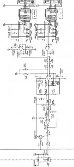
I have plotted the differential output versus the I/V resistors used - attached are the plots.
There are a number of conclusions:
- Low resistor values (28 & 73 ohms especially showed more background noise)
- High resistor values(over 400 ohms) started to show a non-linear response. Not a sharp clipping but the plots show the voltage output started to be limited. This would lead to less dynamic range.
The optimum I/V resistor value for the PCM1702 seems to be in the 300 - 400 ohm range. (see the plots).
Plot1 shows all the test data, You can clearly see the non-linearity and the effect of voltage limiting due to internal protection....
I disconnected the Iout pin from the two PCM1702 DACs in one channel. Each Iout was connected thru a dedicated resistor to signal ground using an old passive balanced shunt resistor volume control which I retired when I converted to TVC.
Then I connected up a dual trace scope to Both the Iouts and looked at the P-P voltages while playing a maximum amplitude test CD.
For a start the DAC outputs were identical but inverted. When I added the signals I just got background noise. When I added the the signals with one channel inverted (ie differential mode) I doubled the output over the single DAC outputs.
I have plotted the differential output versus the I/V resistors used - attached are the plots.
There are a number of conclusions:
- Low resistor values (28 & 73 ohms especially showed more background noise)
- High resistor values(over 400 ohms) started to show a non-linear response. Not a sharp clipping but the plots show the voltage output started to be limited. This would lead to less dynamic range.
The optimum I/V resistor value for the PCM1702 seems to be in the 300 - 400 ohm range. (see the plots).
Plot1 shows all the test data, You can clearly see the non-linearity and the effect of voltage limiting due to internal protection....
Attachments
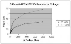
Plot2 shows a zoomed-in version of the same data set, limited to max 400 ohms, this is very much more linear.
For Info, the PCM1702 Iout spec is +/- 1.2 mA
Now I can start to specify the output transformer I need.
Any comments or suggestions welcome.
For Info, the PCM1702 Iout spec is +/- 1.2 mA
Now I can start to specify the output transformer I need.
Any comments or suggestions welcome.
Attachments
Hi,
Since they are balanced you can connect a restistor to each output to gnd and then a transformer connected to both dac outputs (so not to gnd). One of the secondary windings can then be connected to (another) gnd again.
works for me😉
Since they are balanced you can connect a restistor to each output to gnd and then a transformer connected to both dac outputs (so not to gnd). One of the secondary windings can then be connected to (another) gnd again.
works for me😉
- Status
- Not open for further replies.
- Home
- Source & Line
- Digital Source
- VRDS-8 Analog Section Upgrade