Hello DIYAUDIO
please help me....I play the trumpet
and i have Shure PGX4 reciver + Shure PGX1 transmitter + Shure Beta98H instrument electret microphone.
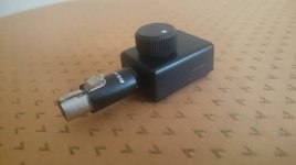
all work good... but...if it possible HELP my to DIY small volume control on my Beta98H cable linke in picture.
its very confortable option for LIVE play on small stage.
i try put one 10k ohm potentiometer on Beta98H cable but it produce a orible noise/scrath wen i turn the pot.
maybe need optional capacitor to avoid the noise, or other wiring diagram???
thanks in advance
please help me....I play the trumpet
and i have Shure PGX4 reciver + Shure PGX1 transmitter + Shure Beta98H instrument electret microphone.
all work good... but...if it possible HELP my to DIY small volume control on my Beta98H cable linke in picture.
its very confortable option for LIVE play on small stage.
i try put one 10k ohm potentiometer on Beta98H cable but it produce a orible noise/scrath wen i turn the pot.
maybe need optional capacitor to avoid the noise, or other wiring diagram???
thanks in advance
Attachments

The electret mic capsule needs a power supply, and that often rides the signal line through the cable. I suspect your control is noisy because of this DC voltage.
thanks for reply Enzo, cotect , realy the DC voltage make my problem...but how to avoid it?
Last edited:
You should start by posting the connector used and a small schematic showing the pins and voltage measured on them relative to pin 1 which is supposed to be ground.
Then I might be able to suggest an AC coupled, DC separated attenuator, somewhat crude but best possible under the circumstances.
That said, the transmitter/receiver "companding" system might make our life miserable 🙁 but let's do the experiment anyway.
Then I might be able to suggest an AC coupled, DC separated attenuator, somewhat crude but best possible under the circumstances.
That said, the transmitter/receiver "companding" system might make our life miserable 🙁 but let's do the experiment anyway.
Last edited:

I'm assuming a couple things here, since I don't know the internal schematic, but here it goes:
1) being a 2 leg electret capsule, it typically should have an internal FET working as a constant current generator, feeding a load resistor at the transmitter.
Such resistors are typically from 2k to 10k and set the gain.
2) paralleling a low value resistor , I can attenuate gain.
3) I want to parallel the external resistor (potentiometer) only for AC (Audio) , not for DC, so I add a coupling cap of approppriate value, in this case 10uF(x 12/16/25V) is fine.
Remember to orient the + terminal towards the +5V line (which carries both DC and Audio, as noted by Enzo) and the - terminal towards ground.
4) when you turn the system on, it *might* scratch a little (anyway way before the earlier level) for, say, a minute, no big deal.
It might scratch somewhat in the future if pot gets *real* dirty, in that case clean or replace it, we are talking months or years into the future.
5) get a Log/Audio pot which will give you a way smoother control.
That said, try it with the current B/Linear one just as a proof of concept.
Enjoy 🙂
EDIT: sorry, forgot to upload the picture somewhere and link it here 🙁
Here it is:
An externally hosted image should be here but it was not working when we last tested it.
Last edited:
ooo big thanks JMFahei.... today i test your schematic...work fine, no scratch, no noise
but in my small city i find only metallized polypropylene capacitors (1uF). its OK??? if it work fine
thanks friend
but in my small city i find only metallized polypropylene capacitors (1uF). its OK??? if it work fine
thanks friend
Cool 🙂
I'm sure you'll *easily* find that cap if you ask for : "an electrolytic cap, 10uF x 25V" .
I guess you omitted that word or tried to find it in the catalog, but living with "the other" caps, not electrolytics.
In fact it's *way* easier to find than a 1uF polypropylene one, and definitely cheaper.
Only caveat is that it's polarized, meaning it has a + leg and a - leg, I showed where each of them goes.
Suggested just because it will be smaller and work better ... did I mention cheaper too ?
And smaller/lighter, what's not to like? 🙂
I'm assuming a couple things here, since I don't know the internal schematic, but here it goes:
1) being a 2 leg electret capsule, it typically should have an internal FET working as a constant current generator, feeding a load resistor at the transmitter.
Such resistors are typically from 2k to 10k and set the gain.
2) paralleling a low value resistor , I can attenuate gain.
3) I want to parallel the external resistor (potentiometer) only for AC (Audio) , not for DC, so I add a coupling cap of approppriate value, in this case 10uF(x 12/16/25V) is fine.
Remember to orient the + terminal towards the +5V line (which carries both DC and Audio, as noted by Enzo) and the - terminal towards ground.
4) when you turn the system on, it might scratch a little (anyway way before the earlier level) for, say, a minute, no big deal.
It might scratch somewhat in the future if pot gets real dirty, in that case clean or replace it, we are talking months or years into the future.
5) get a Log/Audio pot which will give you a way smoother control.
That said, try it with the current B/Linear one just as a proof of concept.
Enjoy 🙂
EDIT: sorry, forgot to upload the picture somewhere and link it here 🙁
Here it is:
An externally hosted image should be here but it was not working when we last tested it.
Sorry, I know it's an old post, but I would also like the scheme for the volume control. the link with the image is expired. thank you very much.I'm assuming a couple things here, since I don't know the internal schematic, but here it goes:
1) being a 2 leg electret capsule, it typically should have an internal FET working as a constant current generator, feeding a load resistor at the transmitter.
Such resistors are typically from 2k to 10k and set the gain.
2) paralleling a low value resistor , I can attenuate gain.
3) I want to parallel the external resistor (potentiometer) only for AC (Audio) , not for DC, so I add a coupling cap of approppriate value, in this case 10uF(x 12/16/25V) is fine.
Remember to orient the + terminal towards the +5V line (which carries both DC and Audio, as noted by Enzo) and the - terminal towards ground.
4) when you turn the system on, it might scratch a little (anyway way before the earlier level) for, say, a minute, no big deal.
It might scratch somewhat in the future if pot gets real dirty, in that case clean or replace it, we are talking months or years into the future.
5) get a Log/Audio pot which will give you a way smoother control.
That said, try it with the current B/Linear one just as a proof of concept.
Enjoy 🙂
EDIT: sorry, forgot to upload the picture somewhere and link it here 🙁
Here it is:
An externally hosted image should be here but it was not working when we last tested it.
Try this:

Here you are shorting output only for Audio but not for DC.
A Linear B10k pot will work, sort of, but volume regulation will be horrible, 0 to 90% within less than 10% rotation, while a Log/Audio A10k will be much smoother.
Here you are shorting output only for Audio but not for DC.
A Linear B10k pot will work, sort of, but volume regulation will be horrible, 0 to 90% within less than 10% rotation, while a Log/Audio A10k will be much smoother.
- Home
- Live Sound
- PA Systems
- Volume Control