Alright.. total newb here - filed under 'the only stupid questions are the ones not asked'...
So, I notice a distinct lack of volume controls on chip amps - including the one I just bought for myself (see my thread, SSI Powerflex).
So, for those amps/devices that have volume controls, what is the volume knob controlling?
Is it controlling the strength of the input signal before it's sent to the amplifier chip, or is it controlling the strength of the signal being sent out of the chip, with the input being constant?
In the former case, does this mean that all chip amps are always running at their full rated multiplication/amplification.. so (values for the sake of easy math) say it's amplifying the signal 10x. if i put in a 1w signal is it outputting 10w? and if i put in a 2w signal does it output a 20w signal?
can anyone explain this simply?
thanks!
The volume control is controlling the incoming signal going to the chip amp.
You are right - the chip amp acts as the "dumb" power amplifier - it take the input signal (in most cases measured in volts as it's too weak to drive some speakers), multiply it by amplification ratio and being able to drive speakers, headphones etc. produces the signal we hear.
So (arbitrary values) - 1V at the input x 10 times amplification = 10V at the output; on 8 Ohm speaker it makes 10^2/8 = 12.5W
And 0.1 V (volume knob turned downwards) will make 1 V, which on the same speaker is 1^2/8 = 0.125W.
Hope it helped.
And to add, it isn't power input, it is volts input at a high impedance (something at least 10k) so power in assuming 1v peak to peak would be 0.0001 watt (v^2/r). The amplifier increases voltage by the gain and buffers the current into a lower impedance (your speakers).
Bored so I thought I would confuse the issue a bit. 🙂
An analogy could be made to volume control pots being equivalent to the throttle in an engine with a governor on it. The signal from the preamp runs at constant gain. The amp runs at constant gain. It is just like you don't vary fuel pressure, volume, or atmospheric pressure in an internal combustion engine to vary its output. The way you control the level of output is by restricting at the interface between the constants. In an internal combustion engine it is with the throttle body, with an amp, it is the volume knob/pot that is just a variable resistor with the wiper controlling how much juice gets from the preamp to the amp. Think of it as a choke point equivalent to a throttle body.
Couple of reasons why convention is to do things this way. For one the preamp stage is typically high gain and sensitive which makes it subject to picking up a lot of noise. They require a lot of shielding and attention to detail to get right. Once they do this, the level of their output is high enough where you don't have to worry<much> about stray signals from local radio stations or florescent lights. Much less tedious to do the amp stage and for a lot of people, myself included, more fun.
Another thing is how linear both preamp and amplifier stages are. They have a sweet spot where they are near linear in their gain. Outside of that range, bad things happen like oscillation or non linear response to input signals => distortion. Once again, an engine analogy: Your car engine may operate efficiently between 800 RPM and 5500 RPM. Try running it at 40 RPM or 10,000 RPM and bad things happen.
Of course if you aren't a gear head, none of this will make any sense to you and I'll apologize in advance.
That makes sense!
On the contrary, i'm a car DIY'er before an audio DIY'er, so that was perfect 😉
The reason I ask really, is that I have my SSI Powerflex connected to my mobile phone via a 1/8" audio plug that splits into two RCA plugs. With max volume on the phone, and max volume on the amp (i'm using the level adjustment on the channel), it's not distorting or blowing the speaker i have connected, which are 6Ω/10W rated. As the TDa1514 is rated for 50w, I thought I would easily be putting out too much for these speakers.
Now, my general thinking is that the audio-out on a mobile phone puts out a substantial amount of power (i mean, enough to to power headphones), and my thought was that it would be much more than a standard device would put out on a pre-out... but i guess that's not the case?
Of course if you aren't a gear head, none of this will make any sense to you and I'll apologize in advance.
On the contrary, i'm a car DIY'er before an audio DIY'er, so that was perfect 😉
The reason I ask really, is that I have my SSI Powerflex connected to my mobile phone via a 1/8" audio plug that splits into two RCA plugs. With max volume on the phone, and max volume on the amp (i'm using the level adjustment on the channel), it's not distorting or blowing the speaker i have connected, which are 6Ω/10W rated. As the TDa1514 is rated for 50w, I thought I would easily be putting out too much for these speakers.
Now, my general thinking is that the audio-out on a mobile phone puts out a substantial amount of power (i mean, enough to to power headphones), and my thought was that it would be much more than a standard device would put out on a pre-out... but i guess that's not the case?
Work in volts and amperes.
Trying to work in watts/powers can become very confusing.
Thanks Andrew.. I knew i was confusing the units and measurements.
Can you tell me what the typical range is for pre-amp output?
Portable devices (mobile phones and mp3 players, for example) do not typically have as high an output as a CD player or television, so it is not surprising that your amp is not playing loudly with a phone as a source.
This is one of those cases where a preamplifier, with gain, is of benefit.
I suspect that if you plugged a standard CD player into your amp it might be a lot less comfortable to listen to!
This is one of those cases where a preamplifier, with gain, is of benefit.
I suspect that if you plugged a standard CD player into your amp it might be a lot less comfortable to listen to!
Watts are awkward to work in as the gain of an amplifier is usually given in volts. And for a given current, watts will be proportional to the square of the voltage.In the former case, does this mean that all chip amps are always running at their full rated multiplication/amplification.. so (values for the sake of easy math) say it's amplifying the signal 10x. if i put in a 1w signal is it outputting 10w? and if i put in a 2w signal does it output a 20w signal?
A chip amp amplifies volts at a rate determined usually by a pair of resistors. Around x20 is typical. Same idea as an op-amp if you know how those work. You select and hardwire those two resistors and your amp is fixed at that amount of voltage gain
It also increases current (usually by a great deal), up to an amount that is somewhat pre-determined, and usually given indirectly by giving the speaker ohmage and voltages it can handle.
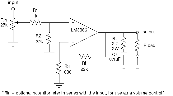
Volume control is just a potentiometer set up as a voltage divider (or a rotary switch version of a pot with a bunch of fixed values if you want greater accuracy) and goes before the chip amp, so it is sometimes thought of as part of a preamp/ input selection circuitry. It's often used to set the amps input impedance too.
Here's a circuit (with some elements missing) with the volume on the far left, as the footnote explains.
Last edited:
A chip amp amplifies volts at a rate determined usually by a pair of resistors. You select and hard wire those two resistors and your amp is fixed at that amount of voltage gain
Thanks Robert... definitely learning something here, awesome!
In the diagram you provided, which two resistors would determine the rate?
Why is changing the gain an option? - I mean, I can understand a scenario where/why you would want to limit the output, but why not just select a lower output chip if that was what the design required?
Could you also have a variable resistor in place of one of those resistors in order to have a variable gain, leaving the input at a set value?
thanks!!
Rf and R3Thanks Robert... definitely learning something here, awesome!
In the diagram you provided, which two resistors would determine the rate?
the formula for gain in this configuration is 1 + Rf/R3, so about x33 in that diagram, which is on the high side.
Because one amp might be designed to be fed by a 0.1 Volt signal, and another by 1 V. There are standards for the input, something called "line level" which means a few different things in different situations, nominally about a third of a volt rms for consumer devices, but seldom stuck to.Why is changing the gain an option? - I mean, I can understand a scenario where/why you would want to limit the output, but why not just select a lower output chip if that was what the design required?
You could, but chip amps are only stable within a narrow range of gains, say x10 to x40. That's a range of 12dB, not enough for a volume control.Could you also have a variable resistor in place of one of those resistors in order to have a variable gain, leaving the input at a set value?
a little background
It might help to realise that the open-loop gain of the chip amp (or op-amp, from operational-amplifier) is incredibly high. So high at audio frequencies, that it is, for all intents and purposes, infinity (it is not, but can be considered so) - it is this high gain which enables us to set the overall gain to our desired level, by varying the amount of negative feedback (which is what you are doing when you take some of the output signal and feed it back, via Rf in this example, to the inverting input.
The high open-loop gain simplifies the maths to the extent that the closed-loop gain becomes down to the ratio Rf to R3.
It is possible to play all sorts of tricks with the feedback: use a series capacitor instead, and you can create an integrator. It is quite possible to use a variable resistor in the feedback loop to vary the gain, but this is fraught with potential problems. Consider the implications of a worn (thus intermittently open circuit) potentiometer. Suddenly you could have moments with no negative feedback - read instability.
In the diagram you provided, which two resistors would determine the rate?
Why is changing the gain an option? - I mean, I can understand a scenario where/why you would want to limit the output, but why not just select a lower output chip if that was what the design required?
It might help to realise that the open-loop gain of the chip amp (or op-amp, from operational-amplifier) is incredibly high. So high at audio frequencies, that it is, for all intents and purposes, infinity (it is not, but can be considered so) - it is this high gain which enables us to set the overall gain to our desired level, by varying the amount of negative feedback (which is what you are doing when you take some of the output signal and feed it back, via Rf in this example, to the inverting input.
The high open-loop gain simplifies the maths to the extent that the closed-loop gain becomes down to the ratio Rf to R3.
It is possible to play all sorts of tricks with the feedback: use a series capacitor instead, and you can create an integrator. It is quite possible to use a variable resistor in the feedback loop to vary the gain, but this is fraught with potential problems. Consider the implications of a worn (thus intermittently open circuit) potentiometer. Suddenly you could have moments with no negative feedback - read instability.
- Status
- Not open for further replies.
- Home
- Amplifiers
- Chip Amps
- Volume Control