Hi,
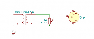
Please look at the schematic.
This is presented as a clone of REDDI DI box in a different forum.
The pot at the output will short the transformer at the extreme position.
Am I missing anything here?
Thank you
Glass painter

Please look at the schematic.
This is presented as a clone of REDDI DI box in a different forum.
The pot at the output will short the transformer at the extreme position.
Am I missing anything here?
Thank you
Glass painter
Not a good idea to mismatch the transformer.
Fit any volume control to the input side of the valve in the recognised way; wiper to the grids or
Fit any volume control to the input side of the valve in the recognised way; wiper to the grids or
Attachments
Last edited:
A level adjustment pot has to be either on the input side of the pre or between the two tube stages.
This 1K pot is at the wrong place and wrong value in the schemo.
This 1K pot is at the wrong place and wrong value in the schemo.
Wrong as drawn
MIGHT work if shorting pot placed across the XLR pins, *after* the 300 ohm resistors R5 and R6 but still the proper way would be to wire it as a non shorting volume control.
Transformer secondary end to end, "ground" and wiper to pins 3 and 2 respectively.
1k pot value is fine there.
MIGHT work if shorting pot placed across the XLR pins, *after* the 300 ohm resistors R5 and R6 but still the proper way would be to wire it as a non shorting volume control.
Transformer secondary end to end, "ground" and wiper to pins 3 and 2 respectively.
1k pot value is fine there.
It is a drawing error. With the pot on the right side of the 300ohm resistors it will work perfectly.
Last edited:
What kind of input voltage is anticipated? Without a level adjustment at input distortion may be higher.
It is a drawing error. With the pot on the right side of the 300ohm resistors it will work perfectly.
No, its not. Its the complete wrong pot type in this application.
If you wish to adjust a symmetric 600 Ohm line then its necessary to put a symmetric 600 Ohm balanced attenuator into it, which reflects always on in- and output the constant 600 Ohm.
As this method is very oldfashioned and out of style, nowadays we put those kind of pots shown here with different values between the voltage amp tube stages.
Thats good design practise. Or maybe on the input of the circuits. But never on the outputs.
If you wish to adjust a symmetric 600 Ohm line then its necessary to put a symmetric 600 Ohm balanced attenuator into it, which reflects always on in- and output the constant 600 Ohm.
The circuit provides a perfect balance, an acceptably low output impedance and does not overload the amplification stage.
It does not have a constant input impedance but does it really matter?
Sorry but you are wrong.
It stays a balanced output for the very good reason that it´s floating, completely unreferenced to ground, it comes from the secondary of a transformer.
If it drives a true balanced input, either active or best, a transformer, it works as intended.
It stays a balanced output for the very good reason that it´s floating, completely unreferenced to ground, it comes from the secondary of a transformer.
If it drives a true balanced input, either active or best, a transformer, it works as intended.
Its not any longer a balanced output
It is balanced. Only i/p o/p impedance is not constant. Does it matter?
It will pass audio and is adjustable.
If we wanted "perfect amplification" we would not be using tubes and iron. Clearly this is an "effect" used to change sound. Flaws are good.
If we wanted "perfect amplification" we would not be using tubes and iron. Clearly this is an "effect" used to change sound. Flaws are good.
Thank you all for the information.
My concern was not to short the output transformer which is never a good thing.
how would this circuit work when the pot is shorting the OP transformer?
Thanks again
Glass Painter
My concern was not to short the output transformer which is never a good thing.
how would this circuit work when the pot is shorting the OP transformer?
Thanks again
Glass Painter
Did you read what you were told above? Move the pot to the right side of the 300ohm resistors and all will be well. For the record, shorting the transformer won't blow anything.
Last edited:
- Home
- Amplifiers
- Tubes / Valves
- Volume at the output of preamplifier matching transformer