Hello
I'm looking for a simple schematic for a voltage regulator which regulates to half of input voltage. It should be small and using less idle current.
A simple schemtic would be

But the problem is that if the current on VCC_HALF is changing then there will be a voltage drop since the transistor does not regulate well and there is still some voltage drop due to Vbe voltage.
Other possibility would be to use an OPAMP but designing a voltage regulator with an OPAMP may not that easy since for capacitive loads it may become unstable.
Does someone know other possibilities how to regulate to half of input voltage or a version with an OPAMP which can handle some uF of capacitive loads.
Thanks
I'm looking for a simple schematic for a voltage regulator which regulates to half of input voltage. It should be small and using less idle current.
A simple schemtic would be
But the problem is that if the current on VCC_HALF is changing then there will be a voltage drop since the transistor does not regulate well and there is still some voltage drop due to Vbe voltage.
Other possibility would be to use an OPAMP but designing a voltage regulator with an OPAMP may not that easy since for capacitive loads it may become unstable.
Does someone know other possibilities how to regulate to half of input voltage or a version with an OPAMP which can handle some uF of capacitive loads.
Thanks
Lower the two 22k resistors to under 10k, add two diodes (1N4148) in series with R67 and make Q2 a Darlington (TO126/TO220 case style).
Plus Nigel's advise.
Plus Nigel's advise.

All excellent points, dreamth, PRR, Citizen124032, Osvaldo, and Nigel. But 'what voltages', me wonders? The rail-splitters are plenty easy to implement, and both Source and Sink well. But we need to know voltages, and current requirements, before reasonably sensible solutions can be offered.
Also, the FMMT617 may not be the best choice if you keep this circuit. Like a lot of Zetex products, the current gain is excellent. But low Vce(sat) values sometimes sacrifice absolute current gain for the better Early gain values.
Cheers
Also, the FMMT617 may not be the best choice if you keep this circuit. Like a lot of Zetex products, the current gain is excellent. But low Vce(sat) values sometimes sacrifice absolute current gain for the better Early gain values.
Cheers
Last edited:
Party-pooper!we need to know
If we wait for someone to say how much power they need, EVER, this place will be a ghost town.
The base of that transistor will need more current as emitter current increases too, dragging down the flimsy voltage divider.and there is still some voltage drop due to Vbe voltage.
Back in the heyday of computer power subsystems, one vendor proposed fixed duty cycle regulators, which depended on the regulation upstream. It didnt catch on, apparently.
However you could do fixed 50% duty cycle driving a high side / low side FET pair, with the usual inductor and capacitor filter - that'd give you half. Drop from half would be due to the resistance of the inductor and Rds on of the FET, which could be pretty low depending on the frequency you can drive the FETs at.
Drive all the capacitance you want - there's no control loop to go unstable. Details like short circuit protection left to the student...
Say, isnt that what any current class D audio amp does, when using ordinary, versus whiz-bang battery power saving modulation scheme? Just sit there at 50% duty with no input signal?
Because most are BTL, you have two outputs just sitting there at 50%. Just ground the audio input and each half of the BTL outputs will give you 50% of whatever Vcc you provide - I've seen an input range of 10 - 30V on some chips.
Bonus - the short circuit protection is taken care of for you...as long as you pick a big enough output inductor to give it time to react. If you choose an assembled amp to do this, it may be a fair assumption whoever designed it accounted for that.
https://www.ebay.com/itm/203803341946 Need 12V from 24? Just short the input, connect it to 24V and I'd bet you see 12V with a DMM at each of the BTL outs. A couple of amps worth on each output. No heat sink necessary. Maybe. But for sure not like you'd need with that linear!
If the Vcc_switch is a known constant, there would be no need for an exact half voltage but use a defined voltage.
For instance, if Vcc_switch =12V, use a $ 0.50 6V integrated regulator and be done.
But yes, it all depends on voltages and currents and that remains a secret, just to make it hard to get to a solution.
People do not understand that the first step to solving a problem would be to explain the problem in some detail.
Jan
Thank you all for your help. I'm impressed what support I get in this forum.
I will add some mor info:
The current needed is not much, around max 10mA under some conditions but quiescent current < 1mA, so the TLE2426 is a very interesting part but unfortunately only SO8 package as SMD.
The problem is that it must be battery powered so quiescent current is crucial.
So decreasing the 22k will make regulation better but increases quiescent current. I played with Darlington in spice simulation but this will not help much also changing the npn transistor to other types will not give much improvement. The offset should be less then 100mV when current changes. Adding diods in series I need to check. Are there alternatives to the TLE2426, seems to be a quite old device?
The input voltegae is around 8V (9V lithium battery) and will change over time, so the half voltage is around 4V. But it is important that it will be always half the input valtage using just a fix voltage will not work.
You could use a very low quiescent current opamp with high value divider resistors, some of those opamps draw only a few 100 uA supply current.
Jan
Jan
Nice to share crucial information after several posts... I hope you get your answer.I will add some mor info:
... The problem is that it must be battery powered so quiescent current is crucial...
If you're in the states, I can send you a few -- TO92 package.The current needed is not much, around max 10mA under some conditions but quiescent current < 1mA, so the TLE2426 is a very interesting part but unfortunately only SO8 package as SMD.
.
Thanks but unfortunately I'm living in Germany but I have ordered two SO8 samples for testing.If you're in the states, I can send you a few -- TO92 package
I was not aware that what I'm looking for is called a "rail splitter". I took a long search for "rail splitter" but I could not find any alterntive for TLE2426.
It seems no other manufacture has developed a similar newer device, maybe with smaller footprint and higher output current etc.
Interesting, comparing with the infinite number of OPMAP versions, no manufacture spent the efford to develop a similar device for such a common problem.
If you're willing to get busy with jewelers' files, you can cut a little almost-square hole in the PCB to fit the flat face of the TO-92. The thickness of many boards is pretty close to the distance from the flat face, to the nearest surface of the leads. Voila' -- pseudo-surface mount! Oh sure, it sticks up a little higher, and you have to solder very carefully, and it's time consuming and a little tedious, but the footprint is a little smaller than the SO-8.
The TLE2426 sounds like the perfect solution, especially when there are strict idle power requirements.
Cheers
The TLE2426 sounds like the perfect solution, especially when there are strict idle power requirements.
Cheers
Why not use 1.5 volt cells? An even number has a natural center-tap.The input voltegae is around 8V (9V lithium battery) and will change over time, so the half voltage is around 4V.
Ed
A 3-wire power supply does slightly complicate power switching. Plus, maybe OP needs something rechargeable.
There is one teeny thing that sometimes crosses up new TLE2426 users -- there's a relationship between load current and load capacitance that needs to be respected.
Regards

There is one teeny thing that sometimes crosses up new TLE2426 users -- there's a relationship between load current and load capacitance that needs to be respected.
Regards
Indeed!There is one teeny thing that sometimes crosses up new TLE2426 users -- there's a relationship between load current and load capacitance that needs to be respected.
Regards
Attachments
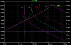
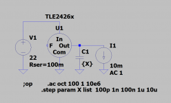
Thanks for that, I have already seen this. With two 4.7uF capacitor to GND and VCC should set it out of the unstable region.There is one teeny thing that sometimes crosses up new TLE2426 users
- Home
- Amplifiers
- Power Supplies
- Voltage regulator for half input voltage