Hi,
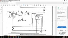
I've got several tube amp builds under my belt and feel I understand the electronics behind them pretty well, but I'm encountering some circuitry I haven't seen before in the power supply of a vintage console amp I'm rebuilding. I've attached a picture of the power supply schemtic.
1. Practically speaking, the most important thing is understanding the grounding of the bottom leg of the PT secondary. I'm not using the output power socket for the tuner, so can I just omit R85, C71, and that's it. Does the circuit complete via C71 to ground with the 310 volts generated at the first stage? All of the circuts I've worked with have grounded 1 leg of the PT directly. Or do I need to rework that slightly? Perhaps just connect the + side of C71 to the - side of C70 floating, and ground both the negative side of C71 and the PT secondary bottom leg to the chassis?
The rest is theoretical, but I'd greatly appreciate an explanation.
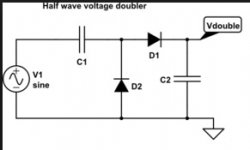
2. Is the 310 volts achieved from the 115v secondary via diodes X1 and X2 and C86? I've researched half wave voltage doublers extensively, but could not find an example where the capacitor was in parallel with a diode to ground. They all look like the attached version, whose operation I do understand.
Thanks!
Joe
I've got several tube amp builds under my belt and feel I understand the electronics behind them pretty well, but I'm encountering some circuitry I haven't seen before in the power supply of a vintage console amp I'm rebuilding. I've attached a picture of the power supply schemtic.
1. Practically speaking, the most important thing is understanding the grounding of the bottom leg of the PT secondary. I'm not using the output power socket for the tuner, so can I just omit R85, C71, and that's it. Does the circuit complete via C71 to ground with the 310 volts generated at the first stage? All of the circuts I've worked with have grounded 1 leg of the PT directly. Or do I need to rework that slightly? Perhaps just connect the + side of C71 to the - side of C70 floating, and ground both the negative side of C71 and the PT secondary bottom leg to the chassis?
The rest is theoretical, but I'd greatly appreciate an explanation.
2. Is the 310 volts achieved from the 115v secondary via diodes X1 and X2 and C86? I've researched half wave voltage doublers extensively, but could not find an example where the capacitor was in parallel with a diode to ground. They all look like the attached version, whose operation I do understand.
Thanks!
Joe
Attachments
You will improve performance by converting to the "full wave" doubler set up. Both transformer efficiency and ripple frequency are implicated. While not truly full wave, the so called full wave doubler does utilize the entire AC waveform and the ripple freq. is 2X the power line freq. OTOH, the 1/2 wave doubler exhibits a ripple freq. = to the power line freq.
Getting rid of unused stuff makes sense to me.
C86 is a snubber (switching noise suppressor). Replace the OEM diodes with much quieter UF4007s. A high WVDC 0.01 μF. cap. connecting the junction of the UF4007s and power trafo to ground will eliminate most of whatever switching noise is produced. Inserting a CL-90 inrush current limiter in the line connecting the power trafo to the center of the doubler stack simultaneously deals with today's higher average AC mains voltage, while allowing for a safe increase in the doubler stack cap. value to 220 μF.
Phase the 2 filament windings up and connect them in parallel. It may be necessary to add some resistance here, in order to deal with today's higher average line voltages. 6.3 VAC +5%/-10% rarely gives you grief.
Thanks Eli! May post a couple follow up points later when I have time but this is awesome. I learned the 6.3 volt + modern wall voltage lesson when a prior build kept popping the 6.3v pilot lamp bulbs before I added resistance so I already know the values 🙂
Based on some rough online guidance, I had intended to put a CL-70 in line with the primary. Would the inrush limiter, be it the CL-70, 90, or other optimal value, in the primary instead of the secondary help with both the heater circuit and the high voltage secondary circuit?
Also, in a configuration like this, does the voltage doubler always double the value of the rectified DC (i.e. 115 x 1.414 x 2)? Most diagrams I've seen just list an input voltage and output voltage that is 2x that value.
Thanks again!
Joe
A doubler yields 2X the RMS voltage times 21/2, less losses. Those losses are significant.
Put the CL-90 on the secondary side, as I stated above. Doing so allows the heaters to warm up somewhat, before full B+ voltage appears. Tubes rarely fail due to the filament (heater) going open. Reduction in emission and other factors lowering gm are the main and inevitable reasons, for tubes becoming non-functional.
Put the CL-90 on the secondary side, as I stated above. Doing so allows the heaters to warm up somewhat, before full B+ voltage appears. Tubes rarely fail due to the filament (heater) going open. Reduction in emission and other factors lowering gm are the main and inevitable reasons, for tubes becoming non-functional.
....understanding the grounding of the bottom leg of the PT secondary. I'm not using the output power socket for the tuner, so can I just omit R85, C71, and that's it. ...
No!
There are two "doublers". The snip you posted is NOT equivalent to what is in your amp. It is already the "full wave" form you have been recommended. C71 is vital.
If you do not need the half-voltage feed for tuner, just snip R85 onward. You probably do need something like the R87 R86 chain for whatever you are building.
Without the tuner load, C70 C71 "should be equal", for penny economy and elegance. If these caps are good, let them stay 100 and 120. Since these caps are surely quite old, use new 220u both places.
I see no real reason to add surge limiting. It has worked this way since 1961. There is 9 Ohms in the PT, the peak surge is 13 Amps, which is not the least strain on wiring or PT. A more complete study says 8A peak first cycle, 2A peak by the 3rd cycle, falling to 1.6A peak 0.6A RMS. It surge-starts easier than a 100W incandescent lamp.
Attachments
So end result should look like the attached modded doubler mock-up?
Joe
Don't forget to ground the negative end of the doubler stack. Of the original PSU, only R87, C71A, R86, and C71B are retained. Increasing C71A and C71B to 68 μF. rates to be a good idea.
Finally, add a proper, 3 wire, safety grounded, power cable and primary side fusing.
Leave the 0.005u there. I omitted it for clarity. I suspect it is more to do with the radio function than anything else. It has no big effect on making DC. As long as it does not short, it does no harm.
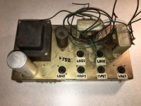
Great. Thanks again to both of you! I can now finalize my parts list and get to work. In hindsight I hope that posting just the power supply portion of the schematic was not too cryptic. Because I wasn't sure the schematic originated from what was effectively an open source, I didn't want to post all of it. The amp is from an early 60's Silvertone console. It's got a 12ax7 input/PI stage into push twin EL84s on each side. Picture attached. As far as the build, I'll add a fused IEC socket, power switch, and volume pot and maybe a pilot light (or just let the tubes suffice!) and RCA/Phono inputs. It's getting a total makeover. All of the original caps, resistors, diodes, wire, terminal strips, etc. are on their way to a landfill. Only the chassis, transformers, and tube sockets are staying and a good portion of the components are going on Fender-amp style eyelet card that I'll make.
There is one other thing that separates this from my builds so far, the lack of a center tap on the heater winding. Is that worth adding (100 ohm resistors on each leg) and, if so, maybe connect it to the cathode voltage on one of the power tubes (assuming it wouldn't create an imbalance between the channels)? My other hi-fi build is a vintage Mullard 3-3 circuit (single ended mono) and they were adamant about this strategy as a way to keep noise to a minimum. Insights always appreciated.
There is one other thing that separates this from my builds so far, the lack of a center tap on the heater winding. Is that worth adding (100 ohm resistors on each leg) and, if so, maybe connect it to the cathode voltage on one of the power tubes (assuming it wouldn't create an imbalance between the channels)? My other hi-fi build is a vintage Mullard 3-3 circuit (single ended mono) and they were adamant about this strategy as a way to keep noise to a minimum. Insights always appreciated.
Attachments
Joe,
I'm out of step with the popularity of IEC sockets. I regard them as just another mechanical connection than can cause trouble and, therefore, prefer "captive" power cables of substantial AWG.
If you take the "full wave" doubler path, 2X of this cap. will make an excellent doubler stack. This part will serve well to snub the UF4007s. You can take advantage of the existing holes in the chassis to clamp mount snap in 'lytics.
"Synthesizing", via 2X resistors, a CT for the phased up filament windings is a good way of killing 2 birds with 1 stone. You create a grounding point and (by adjusting the resistance value) compensate for today's higher average AC mains voltage.
Totally fair point about the IEC sockets. I think I'm going to go with these for the 220ufs. That way I'll keep the inside all the cleaner, and cover up the original cap can mounting holes. A pair of these mounted o a terminal strip on the inside will take care of the rest. I did plug your snubber suggestion into my order sheet. Thank you for reminding me that with the 220s in series, 250 volt ratings would suffice (saved me $10). Furthermore, I'm thinking that high/equal value resistors across each of those 220s to keep voltages across them the same could be tweaked to shave off any extra voltage from the main supply that the CL-90 does not, just like the artificial center tap on the heater winding can help to bring that voltage to spec.
Thanks once more for your help Eli!
Joe
Thanks once more for your help Eli!
Joe
Snap in parts for the doubler stack are fine. As a belt and suspenders thing, put some additional insulating material between the doubler caps. and the mounting clamps. Neither end of the doubler stack's upper cap. is at ground potential.
IMO, you don't need voltage equalizing resistors across the doubler stack. A little extra B+, if present, will not be troublesome. Filament (heater) voltage is another matter. Keeping it within -10%/+5% of nominal makes for "a warm, fuzzy, feeling".
IMO, you don't need voltage equalizing resistors across the doubler stack. A little extra B+, if present, will not be troublesome. Filament (heater) voltage is another matter. Keeping it within -10%/+5% of nominal makes for "a warm, fuzzy, feeling".
The stacked B+ caps do not need equalizing; the rectifier "forces" them to be the same.
(A little off if you suck tuner from mid-point, but not much, and you say you won't.)
One of the heater windings *has* two 100r resistors to ground. Just not drawn clearly. (The whole thing is obviously SAMS, where neat detailing trumped easy understanding.) Unless you have a seriously sick heater, 2*100r is just as good as a CT.
i have a 1960 copy of the ARRL handbook, i picked up a lot of stuff there, you can too if you can get a copy of the book, any edition will do....easily downloaded from the net and for free...
- Status
- Not open for further replies.
- Home
- Amplifiers
- Tubes / Valves
- Voltage Doubling/ PS Grounding in Vintage Silvertone Console Amp Rebuild