Hello!
I have been trying to build a replica of a simple pre-amp from a 1970s era echo machine. It is important to me that, for the moment, I keep the device as close to original design spec as possible.
The op amp, as I have discussed in another thread, is a Toshiba TA7136P. The circuit now is up and running and I am powering its -/+14V spec with two separate 10V DC adapters that measure 14V each under small loads.
I have been researching common ways to power op amps for guitar effects pedal applications and I am wondering if there is a common way to build a voltage divider that responds well to the current demands of an op amp (whatever those typically are). For instance, if I were to power the preamp with a 18V, consumer "pedal power" type device, what circuit would reliably split that into -/+9V for me?
Thanks!
if I were to power the preamp with a 18V, consumer "pedal power" type device,
what circuit would reliably split that into -/+9V for me?
http://www.ti.com/lit/ds/symlink/tle2426.pdf
Wow, this looks promising! Looks like it will halve an input so would I need two of them? How would the negative half work? And two would independently manage their respective + and - without any contact between the two?
Thanks!
Sorry, I got ahead of myself. Looks like the single one will do the job. This seems to be the common way to set it up, right?
http://tangentsoft.net/elec/bitmaps/vgrounds/tle2426clp.png
So, can it be safely assumed that the current draw of this op amp does not exceed 20mA? Sorry for the basic inquiries! 😀
Looks like the max supply current draw is 4.2mA for my op amp....
http://tangentsoft.net/elec/bitmaps/vgrounds/tle2426clp.png
So, can it be safely assumed that the current draw of this op amp does not exceed 20mA? Sorry for the basic inquiries! 😀
Looks like the max supply current draw is 4.2mA for my op amp....
Last edited:
This seems to be the common way to set it up, right?
http://tangentsoft.net/elec/bitmaps/vgrounds/tle2426clp.png
Looks like the max supply current draw is 4.2mA for my op amp....
Yes, this should work ok for you.
Another question about the tle2426: Should the virtual ground be connected to the true ground shared by the rest of the circuit?
Another question about the tle2426: Should the virtual ground be connected to the true ground shared by the rest of the circuit?
Yes, to the output of the TLE2426 circuit.
Yes, to the output of the TLE2426 circuit.
Thanks! How come this circuit is shown with a capacitor? Is that necessary with the tle2426? Will it not work as a stand alone device?
Attachments
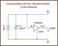
Thanks! How come this circuit is shown with a capacitor? Is that necessary with the tle2426? Will it not work as a stand alone device?
Most amplifiers and regulators need a capacitor on the power supply terminals for proper operation.
- Status
- Not open for further replies.
- Home
- Source & Line
- Analog Line Level
- Voltage Divider for Op Amp