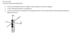
Hello, said that:
1) I'm using FRD and ZMA from manufacturer's EM1308 and 12PFS3 datasheets (i.e. no other mic measurement), after applying the CAD diffraction tool
2) I will put woofer, midrange and tweeter on the same flat front panel
3) The dome of the midrange is wide 60mm (so the top edge of the dome is out around 13mm from the frame by the design) and 2/3 of of the distance of the woofer's coil from the frame is 55 mm (91,3-8,4 * 2 / 3 =55)
Question:
In the VituixCAD crossover tool should I put Z=0 for the 3 drivers, OR should I put Z=+55mm for the woofer and Z=-13mm for the midrange? I'm already put X,Y the relative mounting distance in the panel. But I see many project where people leave 0 to everything...
I'm asking beacause I get totally different frequency responses
Not only: I don't know what to set in the "room" window: distance, rotate, plane, offset....
🙁
Attachments
Once you've set the vertical offset of the LF relative to HF, let Vituix auto-adjust Z and see what you come up with.. Quite often, it'll give you something to work with as a starting point, but do be mindful that manufacturers published specs are often wildly optimistic and nowhere near accurate enough for any kind of predicitions based upon simulation. I've let Vituix a few times manage Z offsets (using measured specs) and occasionally let it adjust a vertical offset when I had some space for it to do so. Accuracy of prediction was excellent overall.. Best of luck with it.
I don't want to optimize, let me explain: I want to simulate a given crossover circuit for the given drivers mounted in the same flat panel (i will not phisically offset).
Question is if I have to leave Z=0 if the curves are taken from the manufacturer datasheets, or put Z=55mm for the woofer?
If you leave Vituix to adjust Z, then it means you should build a tilted louspeaker?
Question is if I have to leave Z=0 if the curves are taken from the manufacturer datasheets, or put Z=55mm for the woofer?
If you leave Vituix to adjust Z, then it means you should build a tilted louspeaker?
It is not possible to reliably simulate a crossover using FRD and ZMA files obtained from manufacturer datasheets because such files contain no phase information and therefore no information about the phase relationships between the drivers of a multi-way loudspeaker. I would only use this approach to assess the feasibility of a project, for example, but not to build a specific crossover or test a finished crossover.
The drivers of a multi-way speaker must therefore be measured and a timing reference must be available. Such measurements also record the Z offset between the drivers, so that the specification for the Z coordinate can remain at 0 for all drivers.
The drivers of a multi-way speaker must therefore be measured and a timing reference must be available. Such measurements also record the Z offset between the drivers, so that the specification for the Z coordinate can remain at 0 for all drivers.

So using only FRD and ZMA without measurements the best simulation would be with Z=0?
I know it is not optimum, just understand which is the best using only datasheet, because changing Z I got a complitely different responce graphs
I know it is not optimum, just understand which is the best using only datasheet, because changing Z I got a complitely different responce graphs
Now you know that you can't set all to zero anyways - because it matters - both in reality and of course in this fine software. It ight not even be enough to set the physical distance... because in the end it is the acoustical center that matters. I frankly don't know if VCAD just want a physical distance and will make an acoustical distance out of knowing the electrical aspects. Probably it does but one need to read the manual or ask the designer here - most probably users here know.
Goof luck the the design.
I would measure the distance from vertical zero to center voice coil and use that as first approximation. Zero for all - it isn't.
//
Goof luck the the design.
I would measure the distance from vertical zero to center voice coil and use that as first approximation. Zero for all - it isn't.
//
Mainly around the crossover frequencies, right?because changing Z I got a complitely different responce graphs
No, this only applies to measured data that contains phase information relative to a common timing reference.So using only FRD and ZMA without measurements the best simulation would be with Z=0?
There is an offset between the sound origins of the different drivers in a multi-way speaker. However, this is not easily predictable. As far as I know, this offset can also vary over the frequency. With data obtained from data sheets, I imagine the specification of any Z-offsets to be like rolling dice.
Azrael is right about the best option being Z=0 with timed measurements.
For factory data you have little choice. You need to add a value for Z.
As Azrael also says, the factory option is less than perfect. I for one rarely listen on-axis. Also, breakup data is no good and the region should be treated with care on factory data.
For factory data you have little choice. You need to add a value for Z.
As Azrael also says, the factory option is less than perfect. I for one rarely listen on-axis. Also, breakup data is no good and the region should be treated with care on factory data.
Usually the tweeter is considered the listening position.
So X, Y can stay at 0.
Then the mid and tweeter would have Y set - negative according to the actual distances you plan on mounting them.
From the 0, 0 position. Which is the tweeter
It is the distance of the driver centers. X also used if drivers are offset.
I usually have a simple cad drawing, so the simulation is exact.
The overall phase relation of each driver changes, so yes it is very important to use correct X , Y
Here is a extreme example if drivers were offset, how X , Y would be set.
Of course not for your example, you need to know your driver mounting positions. X - left + right and Y + up , - down

That is assuming when you did the baffle sim, your Frd was made on center for every driver.
You can also never move the mic and leave it at the tweeter position.
Then sim each driver in correct position and phase will also be correct.
I have done it both ways, but now measure each driver on center in correct position on baffle , then set X , Y for correct phase relation.
So same thing for measuring driver data, I already have a cad drawing and measure each driver exactly where they will be in the real build.
So response info and phase info is correct as possible.
So X, Y can stay at 0.
Then the mid and tweeter would have Y set - negative according to the actual distances you plan on mounting them.
From the 0, 0 position. Which is the tweeter
It is the distance of the driver centers. X also used if drivers are offset.
I usually have a simple cad drawing, so the simulation is exact.
The overall phase relation of each driver changes, so yes it is very important to use correct X , Y
Here is a extreme example if drivers were offset, how X , Y would be set.
Of course not for your example, you need to know your driver mounting positions. X - left + right and Y + up , - down
That is assuming when you did the baffle sim, your Frd was made on center for every driver.
You can also never move the mic and leave it at the tweeter position.
Then sim each driver in correct position and phase will also be correct.
I have done it both ways, but now measure each driver on center in correct position on baffle , then set X , Y for correct phase relation.
So same thing for measuring driver data, I already have a cad drawing and measure each driver exactly where they will be in the real build.
So response info and phase info is correct as possible.
Last edited:
"Here is a extreme example if drivers were offset, how X , Y would be set."
This is exacly what I did. What did you usually put for Z?
It's really not about baffle, but relative VC positions.
A midrange might have its acoustic centre several cm deeper than a dome tweeter.
//
A midrange might have its acoustic centre several cm deeper than a dome tweeter.
//
Measurements are taking from same distance on AES baffle.
That phase information already accounted for.
Z depends if you are actually changing the distance specific to the design.
That phase information already accounted for.
Z depends if you are actually changing the distance specific to the design.
However, manufacturers do not usually provide such phase data. Dayton would be an exception, because Dayton offers FRD and ZMA files for their drivers for download. I took a look at one such FRD file: in addition to the columns for frequency and amplitude, there is also one for phase.Measurements are taking from same distance on AES baffle.
That phase information already accounted for.
So in this case there is a certain chance of being able to accurately simulate a crossover with manufacturer data if a few things are taken into account. In my opinion, however, this would only work if only Dayton drivers were used, and only if all Dayton drivers were measured under exactly the same conditions and with the same timing-reference. It would also have to be ruled out that manufacturing tolerances or production revisions could spoil the fun. (Visaton would be another example of such a manufacturer: Visaton offers such data within the driver database of the Boxsim simulation software)
It would probably not work across manufacturers because the creation of measurements for manufacturer data sheets is probably not sufficiently standardised.
Assuming, however, that everything runs optimally in the aspects I have mentioned, then 0 would have to be entered for the Z coordinate, as well as for my own measurements with timing reference.
But precisely because of these numerous ifs and buts, I clearly prefer to measure the drivers myself in the intended housing.
In my opinion, anything else is not much better than dice rolling.
Last edited:
Phase is no problem since it can be derived from a response plot. Several software packages will trace a random response plot and apply minimum phase data, as Vituixcad will.
The elements which are not minimum phase include diffraction and delay, but we are talking about adding them separately in any case, so no problem.
Of course, if you begin with a single plot there are other limitations like breakup mentioned above.
The elements which are not minimum phase include diffraction and delay, but we are talking about adding them separately in any case, so no problem.
Of course, if you begin with a single plot there are other limitations like breakup mentioned above.
That's true, but how do you intend to establish a common time reference?Phase is no problem since it can be derived from a response plot.
Ok, I see what you're saying now and what I missed. Does Dayton have their measurement scheme outlined on their site?That's true, but how do you intend to establish a common time reference?
There are ways to establish time which I've used without measurement. One is by using a null test on a single tone, by squatting in front of the speaker and standing up while listening for the angle of the null, then calculating back or cross referencing on a simulator.
There are more sophisticated ways depending on the test equipment available.
- Home
- Design & Build
- Software Tools
- VituixCAD woofer and midrange -Z offset