Visaton AL170 in bass reflex box - impedance measurement
Hello all,
I've started a new 2 way project with a combination of Visaton AL170 and G25FFL+WG148. It's going to be a bass reflex system again.
I've made some near field measurements with ARTA, and they looked quite strange, in a sense that I was not able to see the effect of the port.
Therefore, I've taken some impedance measurements for the woofer alone, without crossover, to see where the port could have an effect.
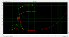
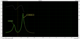
I've attached the impedance measurements for the cases when the port was left open and was closed. What is even more strange is that the measured values are off by around 10 Hz more than I have simulated with Boxsim.
I have not given the box volume on purpose, so that we avoid subjective opinion.
Could you please give me some hints, what it might be wrong?
Hello all,
I've started a new 2 way project with a combination of Visaton AL170 and G25FFL+WG148. It's going to be a bass reflex system again.
I've made some near field measurements with ARTA, and they looked quite strange, in a sense that I was not able to see the effect of the port.
Therefore, I've taken some impedance measurements for the woofer alone, without crossover, to see where the port could have an effect.
I've attached the impedance measurements for the cases when the port was left open and was closed. What is even more strange is that the measured values are off by around 10 Hz more than I have simulated with Boxsim.
I have not given the box volume on purpose, so that we avoid subjective opinion.
Could you please give me some hints, what it might be wrong?
Attachments
Last edited:
imho the two peaks of the red impedance plot should look similarly (equal height).......
the resonant frequency is in the midpoint between the two peaks.
your port is too short or the diameter is too large ?
the resonant frequency is in the midpoint between the two peaks.
your port is too short or the diameter is too large ?
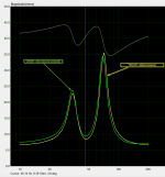
I've did some impedance measurement of both AL170's, in free air. I found that the highest impedance (actually at the natural resonance frequency) is at around 56Hz. I was expecting to be something like 38Hz.
The speakers are brand new, they were never played loud, therefore I think that maybe I'd need to break them in for a couple of weeks before moving forward.
Attached are the measurements, green is one of them, red the other one.
What do you think?
The speakers are brand new, they were never played loud, therefore I think that maybe I'd need to break them in for a couple of weeks before moving forward.
Attached are the measurements, green is one of them, red the other one.
What do you think?
Attachments

yes, the drivers - measured by german speaker magazines - had a break in .........24 hours sinus signals or sowhat.
I've received an interesting feedback on this from the creator of Boxsim, UweG: "In general it is known that new drivers have stiffer suspensions compared to used ones and additionally Thiele/Small parameters depend on the voltage level where they are measured. If you measured with only some mV (e.g. without a power amp) you may get higher fs than at 1 Volt or even 2.83V."
He's right, I was testing with headphone out of my soundcard...
Therefore, I've built the ARTA measuring box tonight, I'll use the power amp to have a much higher level. Tomorrow, measurement day again
He's right, I was testing with headphone out of my soundcard...
Therefore, I've built the ARTA measuring box tonight, I'll use the power amp to have a much higher level. Tomorrow, measurement day again
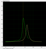
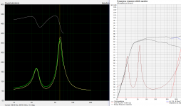
Further impedance measurements done with power amp and Arta measuring box show the one attached below.
I've also added a near field measurement, microphone ~7mm from woofer cone.
Something is still not quite OK.
The box volume is around 39L, without bracing and woofer. I'd expect that these occupy around 2L, therefore I calculate with 37L.
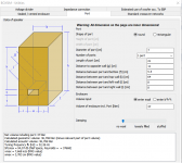
The reflex tube is a flared 7cm piece, cut to 9cm length. This should yield ~37Hz box tuning.
However, the dip on the impedance measurement is at 46Hz...
I've checked the box for leaks, and cannot detect any major issue. Check was done with the BR port tightly closed, the speaker driven at higher volume on 20Hz, and a flame of a lighter driven around the fittings, speaker cutout.
What am I doing wrong here?
I've also added a near field measurement, microphone ~7mm from woofer cone.
Something is still not quite OK.
The box volume is around 39L, without bracing and woofer. I'd expect that these occupy around 2L, therefore I calculate with 37L.
The reflex tube is a flared 7cm piece, cut to 9cm length. This should yield ~37Hz box tuning.
However, the dip on the impedance measurement is at 46Hz...
I've checked the box for leaks, and cannot detect any major issue. Check was done with the BR port tightly closed, the speaker driven at higher volume on 20Hz, and a flame of a lighter driven around the fittings, speaker cutout.
What am I doing wrong here?
Attachments

Al 170 does not meet manufacturer specs. It will not lower to Fs=38 Hz, not now, not ever. At least the units I used to have sure did not. That is your issue.
Al 170 does not meet manufacturer specs. It will not lower to Fs=38 Hz, not now, not ever. At least the units I used to have sure did not. That is your issue.
Then why are they advertising it like that in the first place?
My W170S's seem to perform a bit better, however, they are like almost 10 years old, and the AL170s are brand new.
Anyway, I have followed UweG's advice, and sent an inquiry to Visaton technical department. I'm curious what they are going to answer...
Last edited:
There was a suggestion, that the level on the speaker influences the Fs quite much. Therefore I took a venerable old Tesla ARN567, and did two measurements, one with quite low level, another one with the amp cranked up higher.
60Hz with low volume vs. 43Hz with higher volume! I'll do the same with the AL170 tomorrow, as it is getting late over here...
60Hz with low volume vs. 43Hz with higher volume! I'll do the same with the AL170 tomorrow, as it is getting late over here...
Attachments
I don't know how you arrived on that output, but Unibox tells me that to have a 46Hz tuning in a 37-38L box with walls covered you can use a 7cm flared vent 9cm long. Your measure is pretty consistent with that.The box volume is around 39L, without bracing and woofer. I'd expect that these occupy around 2L, therefore I calculate with 37L.
The reflex tube is a flared 7cm piece, cut to 9cm length. This should yield ~37Hz box tuning.
The box tuning depends only on the box and tube, how this tuning is effective however depends on the driver.
Ralf
There seems to be a widespread conviction on simulations, such as that they do everything right, but it seems more like the reverse applies. So just simulate the simplest and measure the rest.
I don't know how you arrived on that output, but Unibox tells me that to have a 46Hz tuning in a 37-38L box with walls covered you can use a 7cm flared vent 9cm long. Your measure is pretty consistent with that.
The box tuning depends only on the box and tube, how this tuning is effective however depends on the driver.
Ralf
It was Boxsim. However, I now realized I made several mistakes.
The port position was not set correctly. Distance from sides, bottom and top was not filled in, therefore it used the default values.
With the right values I get 43Hz!
Attachments

OK... The issue was wrong Boxsim values.
Now I put in the right values, used a 21cm port, and measured it again.
I get 35Hz from impedance measurement, sim says 32Hz -- therefore it's more or less on the spot.
Boxsim simulated impedance curve also matches the measured ones.
Now I put in the right values, used a 21cm port, and measured it again.
I get 35Hz from impedance measurement, sim says 32Hz -- therefore it's more or less on the spot.
Boxsim simulated impedance curve also matches the measured ones.
Attachments
Last edited:
Got an answer today from Visaton!
Here what they have had to say:
Here what they have had to say:
[FONT="]Here are some ideas:[/FONT]
[LIST]
[*][FONT="]The resonance frequency of a speaker driver is always depending on the power of the signal. The higher the input power, the lower the resonance frequency. On the measurement curves I saw that you’ve used LIMP. At LIMP you can adjust the amplifier volume very easy, so you will get a lower resonance frequency if you put more power into the speaker. In addition LIMP has two possibilities regarding the input signal for the impedance measurement. Either you can use pink noise or a sinus sweep. Please use sinus sweep for the test which gives you more power at one single frequency.[/FONT]
[*][FONT="]Unfortunately I do not know the age of the speaker drivers as well as how and how long they were stored.[/FONT] [FONT="]Sometimes, before the measurement, the speaker must be powered with a sinus tone (try to meet the resonance frequency of the driver) for a while to get all parts in motion. For this, the membrane movement must be as high as possible without destroying the speaker. After this test, the resonance frequency should have went down.[/FONT]
[*][FONT="]For free air impedance measurements the driver should be always placed vertically and fixated very strong to avoid influences of vibration of other parts. In addition the venting hole on the rear side must remain free. If it was measured in a different way, the result could be also different.[/FONT]
[*][FONT="]The resonance frequency is depending on temperature. As an example of another speaker (not the AL 170): At 19°C this speaker had 48,6 Hz; at 0°C it increased to 50 Hz; at 30°C it changed to 46 Hz[/FONT]
[*][FONT="]As usual the resonance frequency also has some tolerances. For the AL 170 the tolerances are: 38 Hz (+20%/-10%) which means the value is between 45,6 Hz and 34,2 Hz. But if you install the speaker into a sealed box, this differences almost doesn’t matter because the Q factor (the damping) of the box is more important than the speaker driver itself, so the values will be smoothed.[/FONT]
[*][FONT="]Regarding the tuning frequency of your 40 l enclosure with 7 cm tube (9 cm length): Unfortunately the statement at most of technical literature is: “It doesn’t matter where the bassreflex tube is located in the box”. But that’s not true! If you place the tube a bit more out of a corner, the tuning frequency will raise up. I made a small simulation with our freeware tool BoxSim (you can download the newest version for free at Boxsim - Homepage and the drivers at BoxSim 2.0: Download Boxsim und Projekt-Datenbank - Visaton Diskussionsforum). If you place the tube into a corner, the resonance frequency is approx. 39 Hz, but if you place it about 10 cm from each wall out of the corner, the resonance frequency increases to 43 Hz.[/FONT]
[/LIST]

It's now 4th order on the woofer.
Ok so you have the parallel LC at the input end, which is a notch of sorts (I guess)
I usually do this with a inductor in parallel with the first capacitor shunt (15uF in your schematic)
Without seeing the sim as a whole and individual filter responses, if guess you would do better with a 4th order HPF too.
But without individual driver responses, it's just conjecture
Last edited:
My apologies, I didn't see the attachment text on my phone.
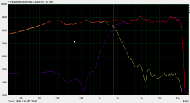
Actually the plot with the black background (,measured?) Shows a good correlation with the Boxsim simulation.
Ignore my previous comments (I also didn't realise the other plot was 5dB/div), it looks like a fairly good end result. You may be able to tweak it some more but it isnt half bad at all.
My first instinct would be to try a 4th order HPF (if it were my speaker), I find it awkward getting phase sounding right with odd order filters
Last edited:
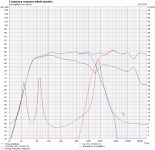
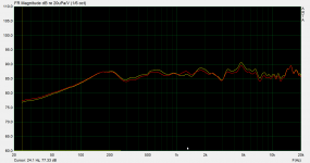
Yes, the plot with the black back is the measured one!
However, I've done now a 3rd order woofer filter, and some tweaks on the HPF.
Find attached. The new crossover is the red line on the measurement, the original one is the yellowish.
Can't understand the dip at 3kHz though... I guess it's from the mike placement, it's from 96cm , centered between the woofer and the tweeter.
Attachments


- Status
- Not open for further replies.
- Home
- Loudspeakers
- Multi-Way
- Visaton AL170 in bass reflex box