Hi, Folks!
Most of DIY amplifier designers have been using audio cards to make audio measurements. This is really cheapest method to get the most important parameters: Frequency Response, THD, THD+N. It provides to get spectrogram and sonogram picture.
The only problem with audio card is that it has a very high linear input sensitivity. Depending on the manufacturer this ranges from 0.5V to 1.5v.
There is a great Test & Measurement interface from Pete Millet, but sometimes we need something very simple.
So I was decided to build a very Simple Attenuator with minimum parts.
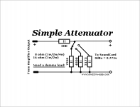
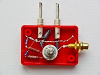
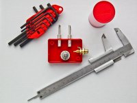
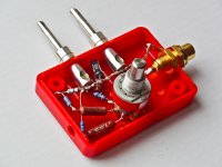
It consists of 9 resistors and 1 rotary switch.
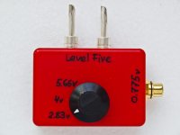
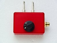
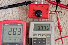
The rotary switch allow to you to switch input voltages between 2.83v, 4v, 5.66v values.
Which corresponds the amplifier output at 1w, 2w, 4w (on 8 ohm dummy load)
and at 1w, 2w (on 16 ohm dummy load).
At the output is configured to produce 0.775v RMS (0 dBu) (unloaded!).
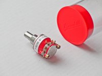
As rotary switch I have used hi-quality made Grayhill 71BD36-01-1-AJN (PDF datasheet).
It looks very solid: 25,000 cycles at rated load, gold-plated rotor contacts, Military Qualified.
As resistors I have chose non-inductive wire-wound Mills. Very well made and not so expensive as Vishay.
The GND must be the same for IN and OUT.
Please see the schematic.
Any comments are welcomed!
Attachments
-
 ba79583c426c8160f3328c0e9e7903e6.png6.6 KB · Views: 551
 -
 e75a6dead3fd2c150968d61fb0d079c9.jpg141.8 KB · Views: 429
 -
 5c2019c3543e5df6216e18ef072a8c6f.jpg133 KB · Views: 397
 -
 attenuator-levelfive-2311.jpg163.5 KB · Views: 397
 -
 1f4d744f5eecc0d70a1aa69b91d4773c.jpg166.5 KB · Views: 375
 -
 a726e74565b6e5740c9d3de7cb998b1a.jpg190.9 KB · Views: 163
 -
 ba700bb0806ba2c343a36fcf2d5e3ccf.jpg132.9 KB · Views: 149
 -
 attenuator-levelfive-5902.jpg209.2 KB · Views: 177
Last edited:
You might want to place a set of diodes antiparallel across the output as clamp protection. Something like cheap red LEDs would not conduct much (uA) at low voltage, but would clamp at 1.6V to protect the sound card input.
Hello, The Gimp!You might want to place a set of diodes antiparallel across the output as clamp protection.
I thought about zener clamp, but fear that it will be itself a source of distortion.
I measured the voltage across a yellow LED with a 470K/470K resistor divider powered from a 1.5V alkaline battery. I only measured .001V difference with the LED across one resistor vs no LED. When I touched the leads my body conductance made for .004V difference.
I think it would not contribute significantly to distortion, but one would have to measure it in the actual circuit to be sure.
I think it would not contribute significantly to distortion, but one would have to measure it in the actual circuit to be sure.
You are right! But Zener diode is semiconductor, which in itself is not good for the "pure" audio circuit....but one would have to measure it in the actual circuit to be sure.
I have read this: Zener diode protects FPGA inputs
The key phrase is:
"Some parasitic effects in the zener diode will create other distortion to the waveform."
And also found this:
The noise of VR tubes is only 1mV of very smooth broadband noise, while the more common Zener diodes have 3 to 5mV of spectrally nonflat noise, occasional LF bumps and pops from "popcorn" noise, problems with temperature coefficients, and a huge amount of grossly nonlinear capacitance.
(c) Lynn Olson
Hello, The Gimp!
I thought about zener clamp, but fear that it will be itself a source of distortion.
Yes, it WILL. Verified.
Do LEDs suffer from the same noise issues?
I think not based on RLD and other use in cathode bias circuits for minimum distortion.
I think not based on RLD and other use in cathode bias circuits for minimum distortion.
Another question is wheter the zeners would produce this noise when they are not conducting (not clamping).
I think not, or a lot less at least 🙂
I think not, or a lot less at least 🙂
Simple THD measurement will tell you almost nothing about the sound and other problems, you need to get into details about harmonic distortion and many more things. Like meassuring input, driver and output stages separately, looking for oscillations, etc.
Let's say you got xx THD, how do you know what adds to your reading? And does it really tell you what to do to get better sound?
For simple meassurements you need at least P.Millet's interface, DWM and oscilloscope. Mr. Millet's description of his interface will give you many hints about measuring with soundcard. I stopped thinking about THD and such things after reading this article:
tvst1
I did't say about only "simple THD measurement" without taking other factors into account. You do not quite understand topics subject.Simple THD measurement will tell you almost nothing about the sound and other problems
And thanks for link 🙂
- Status
- Not open for further replies.
- Home
- Design & Build
- Equipment & Tools
- Very Simple Attenuator For Audio Card