( SOLVED) I was thinking about going active speakers so I thought of making some small multichannel power amps using the LM3886. Used the schematics for here:
https://www.circuitbasics.com/wp-co...-an-LM3886-Circuit-Schematic-with-Diode-2.png
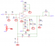
Just changed a few things to use components I have around. Like 10µ in the input and filtering as I have enough of those. I use a UPC1237 for protection so I only put a 30k resistor at pin 8 (mute). PSU is +/- 23V. And I added a 270p between the positive and negative input.
But when I power these up I have a DC offset of 8-9 VOLTS!
First I tought of a bad connection or wrong components. But I now made a second one (without the UPC1237) and I have identically the same thing. Any ideas where to check because this is getting seriously on my nerves.
https://www.circuitbasics.com/wp-co...-an-LM3886-Circuit-Schematic-with-Diode-2.png
Just changed a few things to use components I have around. Like 10µ in the input and filtering as I have enough of those. I use a UPC1237 for protection so I only put a 30k resistor at pin 8 (mute). PSU is +/- 23V. And I added a 270p between the positive and negative input.
But when I power these up I have a DC offset of 8-9 VOLTS!
First I tought of a bad connection or wrong components. But I now made a second one (without the UPC1237) and I have identically the same thing. Any ideas where to check because this is getting seriously on my nerves.
Last edited:
Check your circuit first. But the issue maybe oscillation. Try removing the 270p cap across the inputs.
Also you mention changing the “filtering” cap to 10 ufd. Is that Cc cap?
Also you mention changing the “filtering” cap to 10 ufd. Is that Cc cap?
Does the power supplies measure correctly? One of the Zeners could be shorted or installed backwards.
The 10µ I mention is the Cin and Cs1. I don't have 4.7µ in stock but I do have plenty 10µ of sufficient voltage. I also used 1000µ/100µ/10µ/100n as decoupling, again because in stock.
I would expect removing the 270p to make things worse, not better. Didn't have any 220p, but the datasheet mentions 50-500p so that is stil largely in range.
There are no Zeners in the whole setup. Not in the amp, not in the psu.
At the moment I'm suspecting the LM3886 itself. One duff could be, but two in a row? Or the psu not being up to it. At the moment it is a rather small transformer, I guess about 50-60VA but this is just for testing a single amp. Windings are rectified with 4x BYW29-200 and then 10x 1000µ/50V for each voltage. Again, what was in stock. So it might not be up to powering 4 pieces of LM3886 for active speakers but it should be plenty for checking a single amp.
Maybe fake lm3886's ?
Double check your circuit.
The mute circuit on pin 8 looks strange with a zener, the datasheet circuit just shows a resistor to V-.

Double check your circuit.
The mute circuit on pin 8 looks strange with a zener, the datasheet circuit just shows a resistor to V-.
Last edited:
[quote="nigelwright7557]Maybe fake lm3886's ?
The mute circuit on pin 8 looks strange with a zener, the datasheet circuit just shows a resistor to V-.[/quote]
Have been thinking about that as well. Is almost the only thing left.
I did not use the zener and the capcitor, just a resistor of 33k to Vee (-23V). The power-on delay is done with the UPC1237 on my board.
33k to -23v
If you look at my circuit it says it needs > 1mA to unmute.
You dont have that with 33k !
Try a 22k in place of 33k.
If you look at my circuit it says it needs > 1mA to unmute.
You dont have that with 33k !
Try a 22k in place of 33k.
Offset has been a big issue with these "Overture Series" chipamps. That's why you see a servo in the various BPA designs, and in Bob Cordell's "Designing Audio Power Amplifiers".
Addressing stability, LM3886, LM3875, LM1875 etc very fussy about long "leads" -- mentioned in the datasheet. Really true for the de-coupling capacitors whose leads should be as short as possible.
Ci is much too large, 47u NP, this can cause motorboating and instability.
Check the capacitor Ci, "in situ" for leakage, or just check for DC voltages on the IN+ and IN- pins.
According to the datasheet 0.5mA should be enough to unmute. But I'll give it a try. On the other hand, even if it stays in mute mode it should not put 9V out.
There is offset and offset. A few mV I don't worry about. But this is 9Vdc, enough to fry speakers.
At the moment there are no output leads attached. There is just a 20mm trace on the PC to the output. R//L and RC. The decoupling is 1000µ at 50mm, 100µ at 20mm and 10µ//100n at less than 10mm of the supply pins. Using copper planes of 5mm wide. The power supply is attached with 20cm leads 1.5mm² section.
I have no idea where the Cin of 47µ comes from, my input capacitor is 10µ (X7R) as mentioned above.
Both V+ and V- are at 8-9Vdc.
Offset has been a big issue with these "Overture Series" chipamps.
The typical offset of the LM3886 is ±2 mV. Worst case is ±10 mV. That's not a "big issue". I bet crappy implementations is the big issue.
The schematic linked to in Post 1 should work. You should get no worse than ±10 mV of offset and will probably see around ±2 mV.
You do need Rin or some other DC path from the non-inverting input to ground, however. If you omitted it, that's probably why the amp isn't working.
The stability components are critical. So you do want Rf1 = Rf2 = 20 kΩ (or 22 kΩ); Ri = 1 kΩ; Cf = 50 pF (47 pF is fine too). You want to add 180-220 pF across the inputs of the opamp. 270 pF is probably OK, but I would aim for closer to 2
00 pF.I would make Rm = 27 kΩ for a ±30 V supply. Scrap D1 (just replace it with a wire). Cm = 100-470 uF would be good.
The DC offset will be slightly different between mute and un-mute. But it should still remain within the ±10 mV even when muted.
Tom
If the + input is at 9 volts then the - input will follow it.
I would check the + input circuit going back through the resistors to the ground connection and see what voltages you are getting.
Check the 2 resistor values with your DMM for correct value.
Also check voltage across input electrolytic.
If there is a dc offset across input electrolytic then it needs to polarised the right way.
Last edited:
^^^^^^^^^^^^^^^^^^^^
That.
Check WHY you have +9V DC (or anything above a few mV) at +IN
Absolute worst case short +In to ground.
What happens to output DC?
That.
Check WHY you have +9V DC (or anything above a few mV) at +IN
Absolute worst case short +In to ground.
What happens to output DC?
The typical offset of the LM3886 is ±2 mV. Worst case is ±10 mV. That's not a "big issue". I bet crappy implementations is the big issue.
See TI Application Note 1192.
See TI Application Note 1192.
Check the LM3886 data sheet. The offset numbers are in the spec table, which means that they are measured during production. If the chip does not meet the spec, it is discarded.
The fact that National/TI included a DC servo in the bridge/parallel design does not mean that offset is "a big problem" or that a 9 V offset as experienced by OP is to be expected if a DC servo is not used.
In addition, the LF412 opamp used in the DC servo in the BPA200 design will reduce the DC offset to ±1 mV (typical); ±3 mV (worst case). That's hardly worth it given the ±2 mV typical offset of the LM3886 itself.
Tom
You do need Rin or some other DC path from the non-inverting input to ground, however. If you omitted it, that's probably why the amp isn't working.
The stability components are critical. So you do want Rf1 = Rf2 = 20 kΩ (or 22 kΩ); Ri = 1 kΩ; Cf = 50 pF (47 pF is fine too). You want to add 180-220 pF across the inputs of the opamp. 270 pF is probably OK, but I would aim for closer to 200 pF.
I would make Rm = 27 kΩ for a ±30 V supply. Scrap D1 (just replace it with a wire). Cm = 100-470 uF would be good.
That are the values I used. Didn't put a cap on pin 7 as I do not use the on-delay because I have a UPC1237 doing that. I added 100u to check but this doesn't change anything.
=nigelwright7557]I would check the + input circuit going back through the resistors to the ground connection and see what voltages you are getting.
Check the 2 resistor values with your DMM for correct value.
Also check voltage across input electrolytic.
The values are 20k to GND and 1k in series to IN+ (measured in place). No short to any other part of the circuit. So I have "nothing" over the 1k and 9V over the 20k. Input capacitor is X7R as stated and an 100k to GND at the other side so 9V over it with a 25V rated cap this shouldn't be an issue.
I have no clue why it should have 9V at IN+ because with the 21k in series to GND, even with max bias current I should be at 20mV or so. There is no connection to anything else.
Only thing I can see is a defective LM3886. I can understand having 1 in a batch, but 2 in a row? I ordered 2 from another source. They should be here next week.
If you buy the LM3886 from an authorized distributor (or directly from TI) you will receive genuine parts. They're tested in production, so odds of receiving a defective chip is exceptionally low. Authorized distributors include Mouser and Digikey.
Does the ground connection on Rin connect to circuit ground (so to pin 7 of the LM3886 and all the other grounds)? Or does the ground on Rin only connect to the source output ground?
Tom
Does the ground connection on Rin connect to circuit ground (so to pin 7 of the LM3886 and all the other grounds)? Or does the ground on Rin only connect to the source output ground?
Tom
If you buy the LM3886 from an authorized distributor (or directly from TI) you will receive genuine parts. They're tested in production, so odds of receiving a defective chip is exceptionally low. Authorized distributors include Mouser and Digikey.
Does the ground connection on Rin connect to circuit ground (so to pin 7 of the LM3886 and all the other grounds)? Or does the ground on Rin only connect to the source output ground?
Tom
I'm afraid that my 10 chips won't be the good size order for TI 🙂 Mouser and Digikey are problematic here.
Yes, all grounds are connected. Small signal ones (input, feedback and pin 7) have their separate path to star point of the PSU. Then there is the decoupling ground going back to the same point on the PSU. And speaker return should go from output connector to star ground. But so far there is no speaker connected. Another connection is simply for the output relay and the UPC1237.
Actually, TI will happily sell you QTY = 1. They charge a flat $6.99 shipping (at least to North America).
Odd that it doesn't work for you. I'd double-check the connections. I've built dozens of LM3886 amps exactly like that, though I prefer a different grounding scheme. Once you get the amp to behave properly, have a look here: Taming the LM3886 Chip Amplifier: Grounding – Neurochrome
Star ground vs other grounding schemes is not the cause of your issues. The issue is that you have 9 V on the input to the amp.
Tom
- Home
- Amplifiers
- Chip Amps
- very large DC offset on a LM3886