.
I am working with designing a Very Low Voltage discrete op-amp.
It should be able to operate well at 1.20 - 1.65 VDC = One alkaline AA Battery
I have already created/simulated one circuit that can work at 1.10 Volt ( +- 0.55 Volt )
I have discovered that the lownoise transistors I use, have different level of Vbe.
For example it appears 2SC2240/2SA970 has lower base-emitter voltage than BC550/560 and 2N5551/5401.
😎 I want to know which audio transistors has got lowest VBE 😎
Under low current working conditions and very low voltage.
Say 0.2-2.5 mA and Collector-Emitter voltages of 0.1 - 1.0 Volt.
Lineup
I am working with designing a Very Low Voltage discrete op-amp.
It should be able to operate well at 1.20 - 1.65 VDC = One alkaline AA Battery
An externally hosted image should be here but it was not working when we last tested it.
I have already created/simulated one circuit that can work at 1.10 Volt ( +- 0.55 Volt )
I have discovered that the lownoise transistors I use, have different level of Vbe.
For example it appears 2SC2240/2SA970 has lower base-emitter voltage than BC550/560 and 2N5551/5401.
😎 I want to know which audio transistors has got lowest VBE 😎
Under low current working conditions and very low voltage.
Say 0.2-2.5 mA and Collector-Emitter voltages of 0.1 - 1.0 Volt.
Lineup
Hi Lineup,
That's a tall order 🙂 If it's any use I have circuit for a 3 volt moving coil head amp -- draws 1.5 ma. It's one of JLH's designs and uses a power transistor in common base mode for the input stage. Gives lower noise apparently due to the larger die size in this application.
Regards Karl
That's a tall order 🙂 If it's any use I have circuit for a 3 volt moving coil head amp -- draws 1.5 ma. It's one of JLH's designs and uses a power transistor in common base mode for the input stage. Gives lower noise apparently due to the larger die size in this application.
Regards Karl
3 Volt and 1.5 mA supply current.
Perfect for battery!
I would say making a discrete amplifier for 2 x 1.20-1.65 Volt (2 Batteries) is more attractive and useful.
This way we can use DC-output stage (without capacitor).
Of course, if my op-amp can work at 1.10 Volt (1 Battery)
it is no problem to make it work for 2.00 - 3.30 Volt.
When working at as low voltage as around 1 Volt,
with one input differential pair,
we are almost restricted to only use Inverting Amplification.
With non-inverted input tied to half supply voltage.
This Gives almost constant VCE operation and allows some input voltage span.
Is no coincidence so many Headphone Amplifier Chips, for lower voltages,
shows the typical appplication is INVERTED Amp.
There are a few very low voltage chips, for lower voltage than 2.7 V.
The many with voltage 2.7 is clearly the target value for use in 2 x 1.5 V Battery devices.
... like mp3 players etc.
Hi Lineup,
If you want copy send me an E-Mail. It's not an OpAmp configuration though, it's a a 3 transistor low input impedance design for use with a MC cartridge.
I think Maxim ? may have produced some OpAmps for very low supply voltages in the past.
If you want copy send me an E-Mail. It's not an OpAmp configuration though, it's a a 3 transistor low input impedance design for use with a MC cartridge.
I think Maxim ? may have produced some OpAmps for very low supply voltages in the past.
lineup
Have a look at the LM194/LM394. I understand that they are actually multiple transistors in parallel in both halves. They have a lower than average VBE, and VCE sat. is quite low at 1mA collector current.
Collector to Emitter IC e 1 mA, IB e 10 uA 0.2 typical
Saturation Voltage IC e 1 mA, IB e 100 uA 0.1 typical
SandyK
As I remember, old germanium transistors have low Vbe.
But they have narrow bandwidth, great instability and create a lot of noise... keep them away from audio circuits...
But they have narrow bandwidth, great instability and create a lot of noise... keep them away from audio circuits...
Mooly said:Hi Lineup,
If you want copy send me an E-Mail. It's not an OpAmp configuration though, it's a a 3 transistor low input impedance design for use with a MC cartridge.
Thanks, I wait till you publish it, Mooly 🙂
AndrewT said:try Zetex for low Vbe and low Vcesat
sandyK said:lineup
Have a look at the LM194/LM394. I understand that they are actually multiple transistors in parallel in both halves. They have a lower than average VBE, and VCE sat. is quite low at 1mA collector current.
Collector to Emitter IC e 1 mA, IB e 10 uA 0.2 typical
Saturation Voltage IC e 1 mA, IB e 100 uA 0.1 typical
SandyK. Thanks for info.
But as I think, the LM194/LM394 are very hard to find transistors.
Maybe even obsolete ...
But they are no doubt high class. Super Matched Lownoise Pair .. as I recall.
AndrewT.
Thanks. I will try some of my ZETEX transistor spice models.
And see if they compare lower VBE.
🙂 What are the Lownoise or General small signal transistor devices from ZETEX?
TO-92 standard/higher gain.
Suitable for low level audio circuits?
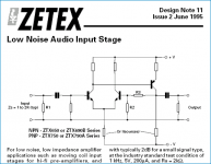
I see in this
ZETEX Application note from 1995
they use ZTX650 npn and ZTX750 pnp
Low Noise Audio Input Stage
http://www.zetex.com/3.0/appnotes/design/dn11.pdf
ZETEX Application note from 1995
they use ZTX650 npn and ZTX750 pnp
Low Noise Audio Input Stage
http://www.zetex.com/3.0/appnotes/design/dn11.pdf
Attachments
lineup said:.
😎 I want to know which audio transistors has got lowest VBE 😎
Lineup
short answer is it (mostly) depends on the batch(s) of trannys you have. measure with diode check on VOM. run 'em nice and very hot and you should get very low Vbe ... kidding !!!
lineup
The dual PNP SSM2220 may be worth a look at too. May not be so easy to come by these days, though.
SandyK
The dual PNP SSM2220 may be worth a look at too. May not be so easy to come by these days, though.
SandyK
SandyK.
I was wrong about LM394.
This super matched low noise pair is still in production.
Strange we do not see these excellent bjt in more hi-fi amplifiers input stages.
AndrewT.
You were absolutely right about ZETEX small signal transistors.
For example when running low voltage simulation,
ZTX689B has got only VBE = 0.505 Volt at 0.5 mA
... this is low base-emitter voltage!
lineup said:SandyK.
I was wrong about LM394.
This super matched low noise pair is still in production.
Strange we do not see these excellent bjt in more hi-fi amplifiers input stages.
AndrewT.
You were absolutely right about ZETEX small signal transistors.
For example when running low voltage simulation,
ZTX689B has got only VBE = 0.505 Volt at 0.5 mA
... this is low base-emitter voltage!
Maybe your model is wrong, as the datasheet shows 0.59V at 0.5mA.
If you want a really low Vbe from your LM394 or any dual transistor, you simply have to use half of the pair as a heather.
With a metal can, you can probably reach 200°C reasonably safely, which will halve the Vbe.
As a bonus, this might confer to your design tube-like qualities, such as "warmth" in the sound (and inside the box too).
LV
With a metal can, you can probably reach 200°C reasonably safely, which will halve the Vbe.
As a bonus, this might confer to your design tube-like qualities, such as "warmth" in the sound (and inside the box too).
LV
my copy of the 689B datasheet (may'94) goes down to 1mA. Tc=25degC &1mA Vbe~=0.5VbeAndy L. Francis said:Maybe your model is wrong, as the datasheet shows 0.59V at 0.5mA.
Elvee said:If you want a really low Vbe from your LM394 or any dual transistor, you simply have to use half of the pair as a heather.
With a metal can, you can probably reach 200°C reasonably safely, which will halve the Vbe.
As a bonus, this might confer to your design tube-like qualities, such as "warmth" in the sound (and inside the box too).
LV
On a single "AA" cell 😉
Elvee said:If you want a really low Vbe from your LM394 or any dual transistor, you simply have to use half of the pair as a heather.
With a metal can, you can probably reach 200°C reasonably safely, which will halve the Vbe.
As a bonus, this might confer to your design tube-like qualities, such as "warmth" in the sound (and inside the box too).
LV
Elvee.
Interesting idea. I remember that one.
Now for BATTERY, one or two, 1.20-1.50 V / 2.40-3.00 V,
we must consider current consumption.
🙂 We want our batteries to last as long as possible.
AndrewT said:my copy of the 689B datasheet (may'94) goes down to 1mA. Tc=25degC &1mA Vbe~=0.5Vbe
AndrewT.
ZTX689B is the device I have put into my low voltage opamp.
It now has been simulated to work rather well at +- 0.500 Volt supply.
The VBE drop is like you say 0.490 - 0.505 Volt.
At least in the spice models I have.
Of course I run my transistors at low currents:
150 uA and to max 500-700uA for the output stage
😎
It is a convential basic opamp =
1. Input differential NPN LTP, two ZTX689B, fead by CCS
---
2. Current mirror on top: Two ZTX718
---
3. PNP VAS=OUTPUT .. right now ZTX718 .. fead by CCS number 2.
Of course use Output from Collectors.
To achieve output like +- 400 mV peak at PSU 1.0 V Battery.
---
4. Both current sources uses ZTX689B with that low VBE drop
and low Saturation Voltage
😎
Notice that if you use rechargable batteries, NiMH 1.2 Volts nominal,
they often have like 1.0 Volt , when empty and need to be charged again.
What is left for me, is to see if anyone of ZETEX NPN transistors
will work better than ZTX689B. ( Less THD % )
For PNP ZTX718 seems to be the best 🙂
FARNELL, UK, sells:
http://uk.farnell.com/9525602/semiconductors-discretes/product.us0?sku=zetex-ztx689b
http://uk.farnell.com/9526536/semiconductors-discretes/product.us0?sku=zetex-ztx718
DATASHEETS: ZTX689B and ZTX718
http://www.farnell.com/datasheets/62411.pdf
http://www.farnell.com/datasheets/58736.pdf
Regards
Lineup .. Sweden July 2008
If current consumption is your main worry, why not look at J201... you'll need more voltage I guess, but you can bias them pretty low...
- Status
- Not open for further replies.
- Home
- Amplifiers
- Solid State
- Vbe Lowest? In lownoise bipolar transistors