I need some varistor diodes that appear to be obsolete.
1.3V, - 4mV/degC.
Both the the original Hitachi KB265 and the Panasonic MA2C029WB appear to be obsolete and not available anywhere.
Does anyone know of a source for these or for an equivalent diode?
Thanks
1.3V, - 4mV/degC.
Both the the original Hitachi KB265 and the Panasonic MA2C029WB appear to be obsolete and not available anywhere.
Does anyone know of a source for these or for an equivalent diode?
Thanks
Well I'm going to hold my hand up and say I have never heard the term "varistor diode" before.
Your description 1.3V, - 4mV/degC. sounds like a series connected pair of silicon PN junctions... in other words two diodes in series. Around 2.1mv/K is the temperature coefficient of a silicon junction so 4mv/K and a volt drop of (2*0.65v) sounds just like two diodes.
Are they used for biasing an amplifier output stage ?
Here you go:
http://www.datasheetcatalog.org/datasheet/panasonic/MA2C029WA.pdf
Panasonic calls it a variable resistor. Philips calls it a "stabistor". We call it hood, they call it bonnet 🙂
It's an epitaxial diode with a tightly controlled and specified forward drop and temp coefficient of the drop. It comes in many voltages and coefficients, not necessarily multiples of a "diode drop".
Thanks for the link...
Don't know what to suggest really. Depends what its used for exactly. Maybe investigate using a programmable diode or an arrangement similar to a normal vbe multiplier but using a resistor to modify the characteristic.
Without seeing the application its hard to advise 🙂
Don't know what to suggest really. Depends what its used for exactly. Maybe investigate using a programmable diode or an arrangement similar to a normal vbe multiplier but using a resistor to modify the characteristic.
Without seeing the application its hard to advise 🙂
The diode is indeed used for bias, in the phase splitter. It is NOT thermally coupled to the transistor it biases, only in the general vicinity. It is hard for me to guess the original intent of using a special part as opposed to the regular diodes they used in the driver stage.
The diode is indeed used for bias, in the phase splitter. It is NOT thermally coupled to the transistor it biases, only in the general vicinity. It is hard for me to guess the original intent of using a special part as opposed to the regular diodes they used in the driver stage.
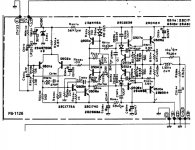
Maybe post the circuit so we can advise better ?
🙂
That should be an easy one to resolve... but lets just go over the theory and try and do it properly.
Q503 is a constant current source in a classic text book arrangement. Now you mentioned that these diodes can have a volt drop other than the normal multiples. Just studying the data sheet, and its almost as though these are diode multiples but with a series resistor too. Just looking at the forward volt drops at 1.5 and 50 milliamps in thinking that. In your amp the current in the diode is constant and so the volt drop (whatever it is) is essentially constant too.
So first question, is the other channel OK and if so can you measure the drop across a known good one ?
Two normal diodes would give around 1.4volts. Subtract the 0.7 base-emitter drop of the transistor and you have 0.7 volts across 150 ohms. Around 4.6 milliamps in other words.
Also is Q504 in thermal contact with the output transistors ? Thats the normal 99.999% of the time way of ensuring thermal stability with a normal vbe multiplier. I can't really see the tempco of the double diode being used in this regard as a means of control.
Using two diodes (perhaps with additional series resistor) and altering the value of the 150 ohm would allow you to set the current to any desired value.
It is vital that the preset is readjusted to give the correct output stage current as even a tiny change in the absolute value of the current flowing in Q503 will alter this.
Mooly, as I stated previously, the varistor diode is not in thermal contact with any transistor, just placed physically next to the transistor it's biasing (Q503).
The other channel was functional, but the way the power board is attached to the power transistors/heat sink and chassis, and the many connections, make it a long ordeal to connect/disconnect everything for testing. I also have no certainty that the other channel has the original part, so I'm going to replace both.
The KB-265 data sheet suggests that the forward drop is less than 2 diode drops, so perhaps it was selected specifically for its forward drop rather than thermal characteristic. I can only guess at the intent, so I would rather find an original or equivalent part.
It was Q504 that I was wondering over being in thermal contact with the outputs 🙂
If you are replacing both diodes then you have two choices...
Either obtain the originals or fit two diodes and confirm the circuit operates correctly.
Have you any concerns with doing that because there is no risk ? I would just advise the bias pots be set initially to minimum bias (which is max resistance of pot) first.
The data sheet in your link shows MA2C029WB as having a drop of 1.26 to 1.36 volts at 3milliamps. Thats bang on the mark for two series diodes. Not sure what voltage your amp runs on but with 63 volt caps I would guess say -/+40 volts. That gives around 2 milliamp through the diode... perfect.
Sorry misread your post. Yes Q504 is sort of in contact🙂 Not in actual contact but visibly bent over by design to a position close enough to the heatsink. About 2 mm away.
I'll try some general diodes on the bench and see if I can get that exact voltage. I'm reaching dead ends finding the original parts. Yes it runs 40-some volts rails.
So why this special part if all they needed was 2 regular diodes? That really nags me and I fell like there may be more to the story...
Sorry misread your post. Yes Q504 is sort of in contact🙂 Not in actual contact but visibly bent over by design to a position close enough to the heatsink. About 2 mm away.
No problem 🙂
What is the actual amplifier make and model of this thing too ?
Q504. Near but not touching... hmmm. That seems a bit strange tbh. Is it possible the amp has been worked on before as you mention the diodes may not be original ?
Normally the vbe multiplier is in very good thermal contact with outputs/heatsink and is normally the method of maintaining thermal stability in 99.9999% of amps.
I have come across an amp (could have been Arcam ? not sure) that did use a weird method of thermal tracking of the output stage rather than the normal methods.
So I think what you have to do is this...
1. Fit two series connected diodes in place of the original. Use IN4148's or similar. No point trying to select them, the volt drop is down to the physical properties of silicon. They will give a value of around 4.6ma as mentioned flowing in the constant current source. Again that value is in exactly the correct ball park for a "typical" amp.
2. Turn down the bias pot as mentioned. (Its good practice to use a bulb tester when working on anything like this... 100 watt bulb in series with mains.)
3. Switch on and confirm all OK. See if the preset adjusts correctly and allows correct output bias. (If using a bulb tester the bulb should start to glow).
Providing there are no other faults the amp will work. There is absolutely no doubt over that.
The only question mark is over thermal stability and trying to get the constant current value at the correct "original design" value. Thats something thats easily altered.
--------------------------------------------------------------------------------------------
For curiosity you could remove the good diode and test the volt drop using say a 9 volt battery and a 3.9 or 4.7k series resistor.
Luxman R1120 receiver. May have been repaired before, but not modified in any obvious way. Has been in my possession for many years and one channel blew recently, for unknown reasons. No fuses blown. Most of the transistors in that channel blew, haven't tested the finals yet, waiting for some other parts.
The way Q504 is mounted is by design. There is a channel in the heatsink and Q504 is on the edge of the board, long legs, then bent over to fit inside that chanel, without touching anything. Q504 is a TO92 package.
Yes, long term stability is an issue, as the amp self-destructed for no apparent reason. Not a particularly robust design if you ask me.
But I agree, at this point looks like I have no choice but to use a couple of 1N4148s.
Thanks...
I think for now fit the diodes and aim to get it working. If Q504 is in a channel in the heatsink then its obviously designed to get hot with the outputs. It may be worth thinking of actually putting it in thermal contact with the heatsink... something to investigate when the amp is working.
I think for now fit the diodes and aim to get it working. If Q504 is in a channel in the heatsink then its obviously designed to get hot with the outputs. It may be worth thinking of actually putting it in thermal contact with the heatsink... something to investigate when the amp is working.
- Status
- Not open for further replies.
- Home
- Design & Build
- Parts
- Varistor diodes?