0.1uF voltage rating 2.5 to 3 times or better if size permit of incoming AC voltage ( from secondary coil of transformer).Alternatively you can parallel another 0.01uF for higher frequency.
0,1 uF
Hi,
0,1 uF is generaly recommanded. I use Wima MKS4.
Low swiching noise diodes are also welcome. There is a nice article by John Camille about this topic in Sound Practices #7.
Alain
Hi,
0,1 uF is generaly recommanded. I use Wima MKS4.
Low swiching noise diodes are also welcome. There is a nice article by John Camille about this topic in Sound Practices #7.
Alain
I experimented some configurations (not simulations!)
A diode bridge should have a behaviur similar to a 1N4007 bridge, I found it best smoothed by 1ohm+22nF // 100nF across the secondary connection to the bridge. It's useless to put a snubber across each diode.
A diode bridge should have a behaviur similar to a 1N4007 bridge, I found it best smoothed by 1ohm+22nF // 100nF across the secondary connection to the bridge. It's useless to put a snubber across each diode.
Hi,
The diode manufacturers say otherwise (when they care to be informative).It's useless to put a snubber across each diode.
mrjam said:I experimented some configurations (not simulations!)
A diode bridge should have a behaviur similar to a 1N4007 bridge, I found it best smoothed by 1ohm+22nF // 100nF across the secondary connection to the bridge. It's useless to put a snubber across each diode.
depends upon the transformer -- and the voltage -- the frequency of the resonant circuit formed by the diode junction capacitance, and the leakage inductance, the ESR and ESL of the filter caps. the diode junction capacitance is a function of voltage (that's how we get diode tuning).
you can start off by measuring the transformer leakage inductance, but this is only a starting point...
depends upon the transformer -- and the voltage
.......
Sorry, I omitted to say: "in my test configuration" 😀
The diode manufacturers say otherwise (when they care to be informative).
I trust in my Tek digital storage 'scope! 😉
With this net - in this test configuration - the oscillation is better smoothed.
Are you sure your manufacturers refer to standard diode bridges? ..or you're talking about SBVY or MUR series. In my tests - with my test configuration naturally - the former are best smoothed by a 22nF across each diode. RC doesn't give any improvement.
All I mean is that the RC snubber across each diode is not always the best solution. Let measure it ...but it's reaaaly difficult without a storage oscilloscope.
Next week I will have access to an exceptional tool, a 20000bucks Advantest R3131 3GHz Network/Spectrum Analyzer, so new measurements have to come. I'll let you know the results of the snubbering on the wide RF spectrum.
Hi Jackinnj
---you can start off by measuring the transformer leakage inductance, but this is only a starting point...---
How to ?
---you can start off by measuring the transformer leakage inductance, but this is only a starting point...---
How to ?
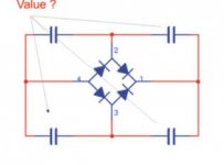
Let's just look at it as an RF circuit with just R,L and C and the Multisim Bode Plotter -- In order #1 is unsnubbed, #2 uses 1R+22n//100nF across the secondary (as suggested by MRJAM), #3 uses 500R+1nF across each Cjo
An externally hosted image should be here but it was not working when we last tested it.
An externally hosted image should be here but it was not working when we last tested it.
An externally hosted image should be here but it was not working when we last tested it.
forr said:Hi Jackinnj
---you can start off by measuring the transformer leakage inductance, but this is only a starting point...---
How to ?
It is only a starting point --
To measure the leakage inductance of the secondary short together the primary leads THEN measure the inductance of the secondary.
Hi Jack,
for me and any others that might mis-interpret your posted sims. Please confirm which is best and which is worst.
for me and any others that might mis-interpret your posted sims. Please confirm which is best and which is worst.
- Status
- Not open for further replies.
- Home
- Amplifiers
- Power Supplies
- Value for capacitors over the diodes to prevent from high frequency