Apologies if I am missing something silly.
I am a mechanical engineer and don't have much knowledge of electronics theory .
I have a Paradigm PW Amp which is a 2.1 channel streamer.
Unfortunately a recent brownout caused a blowout in the SMPS section.
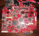
The Amp has two boards - An upper board which has the SMPS and a TDA8954J Amp
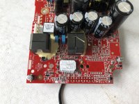
The lower board (Pre-amp : see attached) contains the bits which are more valuable to me (play-fi streaming, Anthem Room correction etc)
The boards are connected via a 20 pin connector (see attached)
I was able to power on the Preamp with an external power supply and it works fine.
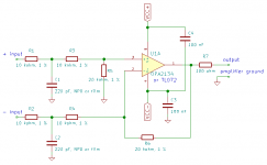
I then identified the Pre-amp out connectors by tracking back the TDA8954J IN1P, IN2P, IN1M and IN2M pins to the connector (IN1P = input 1 positive)
The only components on the track are 4.7K resistors in series and two unidentifiable capacitors. (See attached)
The good news is that connecting the IN1P and IN2P connectors to another Class D Amp works fine
The bad news is that there is a distinct electrical noise at low db levels which is distinct from the typical class D hiss
To explain further:
a) If say class d hiss is at -90db, this is at least 5 db more
b) The noise increases when there is increased electrical activity on the pre-amp e.g. when the wifi board on the pre-amp is searching for a connection at startup
c) The noise is difficult to describe but it is white noise peppered with irregular pops and clicks
I have the Pre-out connected directly to the Pre-in of the amp with the assumption that the standalone amp will have a RC network of its own anyway
I tried with a couple of different amps (Sure electronics TAS5630, an analog marantz Pm-17 ) but the noise remains.
Any thoughts or suggestions?
I am a mechanical engineer and don't have much knowledge of electronics theory .
I have a Paradigm PW Amp which is a 2.1 channel streamer.
Unfortunately a recent brownout caused a blowout in the SMPS section.
The Amp has two boards - An upper board which has the SMPS and a TDA8954J Amp
The lower board (Pre-amp : see attached) contains the bits which are more valuable to me (play-fi streaming, Anthem Room correction etc)
The boards are connected via a 20 pin connector (see attached)
I was able to power on the Preamp with an external power supply and it works fine.
I then identified the Pre-amp out connectors by tracking back the TDA8954J IN1P, IN2P, IN1M and IN2M pins to the connector (IN1P = input 1 positive)
The only components on the track are 4.7K resistors in series and two unidentifiable capacitors. (See attached)
The good news is that connecting the IN1P and IN2P connectors to another Class D Amp works fine
The bad news is that there is a distinct electrical noise at low db levels which is distinct from the typical class D hiss
To explain further:
a) If say class d hiss is at -90db, this is at least 5 db more
b) The noise increases when there is increased electrical activity on the pre-amp e.g. when the wifi board on the pre-amp is searching for a connection at startup
c) The noise is difficult to describe but it is white noise peppered with irregular pops and clicks
I have the Pre-out connected directly to the Pre-in of the amp with the assumption that the standalone amp will have a RC network of its own anyway
I tried with a couple of different amps (Sure electronics TAS5630, an analog marantz Pm-17 ) but the noise remains.
Any thoughts or suggestions?
Attachments

You could try an amplifier with a differential input, if you have or can borrow one. According to your schematic, the original amplifier also had a differential input. Are there RC low-pass filters at the inputs of the other amplifiers, like on the original?
You could try an amplifier with a differential input, if you have or can borrow one. According to your schematic, the original amplifier also had a differential input. Are there RC low-pass filters at the inputs of the other amplifiers, like on the original?
Thanks for the tip - it got me looking in the right direction.
I did have an error on my connections as I was using the ground line on the preamp for the amplifier-In
Changing that the signal ground fixed the noise problem.
However, as you rightly pointed out, the o/p from the pre-amp is differential which I am feeding into single ended.
While the audio quality is good, all imaging seems to be lost (e.g. vocals are diffused rather than seeming to come from between the speakers)
Are there any recommended amplifier boards that accept a differential signal?
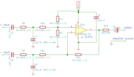
As an alternative, you could consider making a simple differential amplifier plus low-pass filter with an op-amp, six resistors and two capacitors per channel, and feed the output into the amplifier board you already have.
As an alternative, you could consider making a simple differential amplifier plus low-pass filter with an op-amp, six resistors and two capacitors per channel, and feed the output into the amplifier board you already have.
That is actually a great idea.
However one update - I played back a track and measured the voltage levels between the signal + and signal ground and and as expected it moved between a few mV to 70-80 mV
However the signal negative and signal ground was a flat 7.8mV regardless of playback leading me to believe that the o/p from pre-amp is actually not differential
Not sure what a flat voltage on the signal negative line to the amp is supposed to achieve though
Last edited:
I posted post number 6 before reading post number 5.
It could be some kind of quasi-differential connection, where the negative signal line is connected to the best available ground point via an impedance that mimics the impedance of the positive signal line. Then again, the schematic you posted in post number 1 is asymmetrical for some reason or other: C1 is between INIP and INIM and C2 goes from INIM to ground.
It could be some kind of quasi-differential connection, where the negative signal line is connected to the best available ground point via an impedance that mimics the impedance of the positive signal line. Then again, the schematic you posted in post number 1 is asymmetrical for some reason or other: C1 is between INIP and INIM and C2 goes from INIM to ground.
I posted post number 6 before reading post number 5.
It could be some kind of quasi-differential connection, where the negative signal line is connected to the best available ground point via an impedance that mimics the impedance of the positive signal line. Then again, the schematic you posted in post number 1 is asymmetrical for some reason or other: C1 is between INIP and INIM and C2 goes from INIM to ground.
The schematic (which is the schematic from the datasheet of the TAS5630).
It seems Paradigm may have deviated from that.
For now, I have grounded the INIM line via a 10K resistor (to mimic INIP) and the device seems to be working fine.
I still have a feeling that the imaging is off but i could be wrong
z
Figured it out - There is some kind of inversion happening on the original amp board (or maybe the pre-amp o/p is negative biased against signal ground) that was causing an inversion on the o/p going to the speakers.
that is what was messing up the imaging (vocals sounded dispersed rather than center)
Reversing the speaker terminals fixed it and now the imaging is spot-on!
If I had a oscilloscope, this may not have taken so long.
Thanks for pointing me in the right direction again. Cheers!
I posted post number 6 before reading post number 5.
It could be some kind of quasi-differential connection, where the negative signal line is connected to the best available ground point via an impedance that mimics the impedance of the positive signal line. Then again, the schematic you posted in post number 1 is asymmetrical for some reason or other: C1 is between INIP and INIM and C2 goes from INIM to ground.
Figured it out - There is some kind of inversion happening on the original amp board (or maybe the pre-amp o/p is negative biased against signal ground) that was causing an inversion on the o/p going to the speakers.
that is what was messing up the imaging (vocals sounded dispersed rather than center)
Reversing the speaker terminals fixed it and now the imaging is spot-on!
If I had a oscilloscope, this may not have taken so long.
Thanks for pointing me in the right direction again. Cheers!
Last edited:
- Status
- Not open for further replies.
- Home
- Source & Line
- Analog Line Level
- Using the PreAmp section from a Paradigm streamer- Electrical Noise problem