Hi
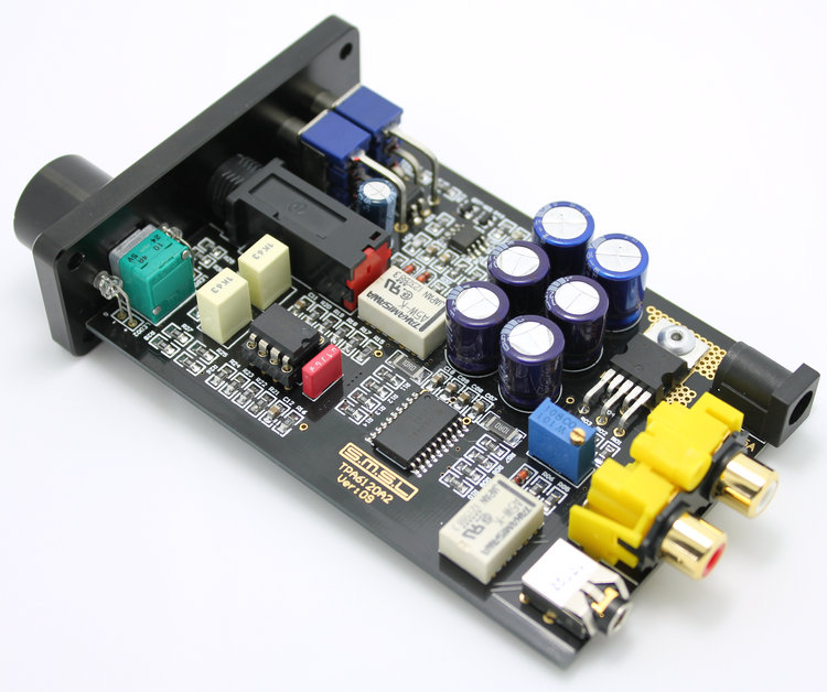
I've inherited an SMSL sApii Pro headphone amplifier with a 24V power supply. This is the first time I’ve been able to listen to the CD Player in my bedroom with headphones! It has both a OPA2604 and a TPA6120a2 chip. But my headphones are only 50 Ohms and it’s right at the bottom end of the volume knob before it gets too loud. It seems to sound really nice but there does seem to be quite a bit of channel imbalance. So, being totally non-technical it seemed the most obvious answer would be to use a lower voltage power supply so that it would be less powerful and therefore I could use more of the volume adjustment. I was thinking of either a 19v laptop supply or a 12v lead acid battery. As far as I am able to tell both of the op amps in the amplifier seem to work at those voltages. But I’m sure there’s lots of other things beyond my understanding to consider before jumping in and trying it out. Could anyone let me know whether it might work at all and if I could do permanent damage to the amplifier. Thanks in advance!

SMSL sApII Pro TPA6120A2 HiFi Stereo Headphone Amplifier AMP:
Specifications:
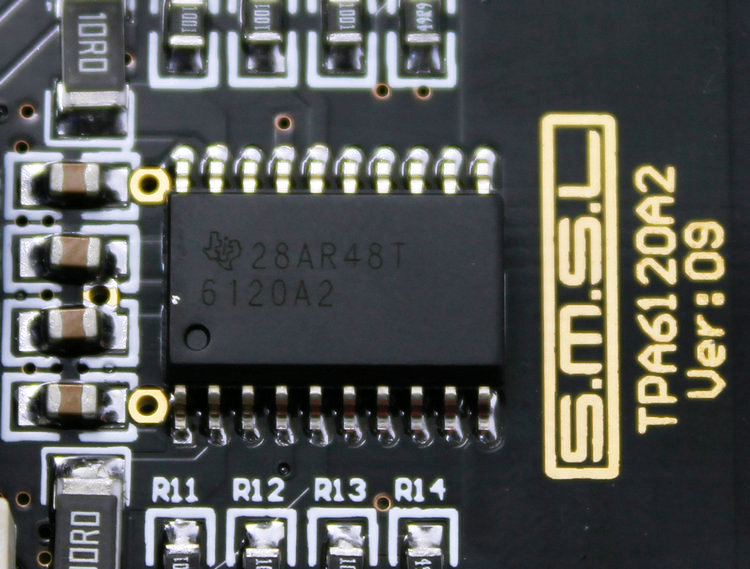
IC: TPA6120A2,OPA2604.
Output power: 90mw/600Ω; 180mw/300Ω; 450mw/100Ω; 610mw/62Ω; 910mw/32Ω; 1000mw/16Ω.
Distortion: <0.003%.
SNR: ≥105dB.
Headphone impedance: 16Ω~1000Ω.
Frequency response: 20Hz-30KHz.
Input: 3.5mm/RCA; Output: 6.35mm.
Machine dimension: approx. 126 x 74 x 30mm".
Weight: approx. 0.5kg.
I've inherited an SMSL sApii Pro headphone amplifier with a 24V power supply. This is the first time I’ve been able to listen to the CD Player in my bedroom with headphones! It has both a OPA2604 and a TPA6120a2 chip. But my headphones are only 50 Ohms and it’s right at the bottom end of the volume knob before it gets too loud. It seems to sound really nice but there does seem to be quite a bit of channel imbalance. So, being totally non-technical it seemed the most obvious answer would be to use a lower voltage power supply so that it would be less powerful and therefore I could use more of the volume adjustment. I was thinking of either a 19v laptop supply or a 12v lead acid battery. As far as I am able to tell both of the op amps in the amplifier seem to work at those voltages. But I’m sure there’s lots of other things beyond my understanding to consider before jumping in and trying it out. Could anyone let me know whether it might work at all and if I could do permanent damage to the amplifier. Thanks in advance!
SMSL sApII Pro TPA6120A2 HiFi Stereo Headphone Amplifier AMP:
Specifications:
IC: TPA6120A2,OPA2604.
Output power: 90mw/600Ω; 180mw/300Ω; 450mw/100Ω; 610mw/62Ω; 910mw/32Ω; 1000mw/16Ω.
Distortion: <0.003%.
SNR: ≥105dB.
Headphone impedance: 16Ω~1000Ω.
Frequency response: 20Hz-30KHz.
Input: 3.5mm/RCA; Output: 6.35mm.
Machine dimension: approx. 126 x 74 x 30mm".
Weight: approx. 0.5kg.
Last edited:
What you really want is lower gain - this will allow the volume control to be used where its channel matching is better, they normally suck at low levels. Using a lower voltage supply won't lower your gain.
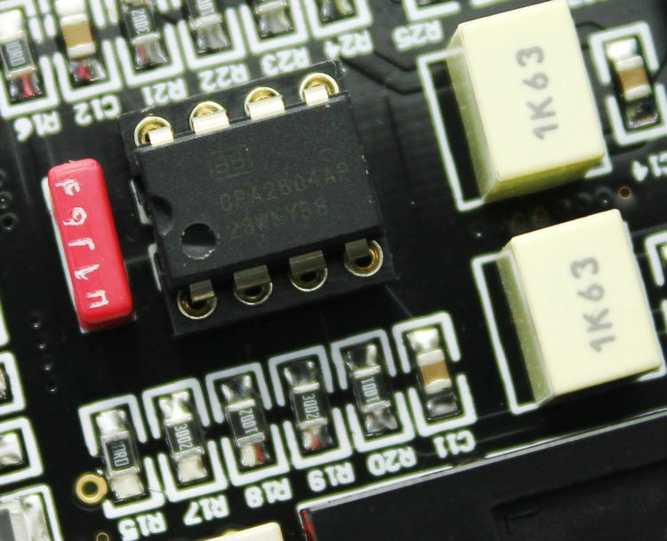
Possibly the OPA2604 is being used as an input amp and has been given gain - the resistors closest to it will be gain setting resistors so hopefully changing a couple of those (or paralleling with additional ones) will sort out the gain issue.
Possibly the OPA2604 is being used as an input amp and has been given gain - the resistors closest to it will be gain setting resistors so hopefully changing a couple of those (or paralleling with additional ones) will sort out the gain issue.
Last edited:
abraxalito,
I've read that the OPA2604 is used for gain and the TPA6120a is used as a buffer - I don't know what a buffer is! To change the resistors will I need to do any soldering?
Just to go back briefly to the voltage question - I understand it currently gives out about 20Vpp - if I'm using a 12V supply is it correct that the most it could give out would be 12V?
A buffer is an amplifier with a voltage gain of *1 - i.e. unity. No voltage gain but provides current gain.
To change resistors yeah you'll need to do a bit of soldering.
You're correct on the voltage question - limiting the supply voltage most certainly limits the maximum output, but recall you're using your volume control down low, so nowhere near maximum output (which would deafen you). So this is kinda irrelevant - maximum output voltage is only going to be needed by those with 600ohm phones who like to listen loud.
Thanks for explaining what a buffer is - I'd not been able to find an explanation anywhere.
There seems to be 4 resistors labelled R1-R4 - are these the gain resistors? do they add together cumulatively e.g. R2 amplifies R1 and then R3 amplifies R2 etc.?
If the output voltage was say 10v rather than 20V wouldn't that apply all the way around the volume dial to give me more adjustment even at the bottom end?
Do you have a close-up pic of your amp showing the OPA2604 and surrounding circuits? I looked on Taobao but the SMSL amps they're showing there don't look to be 'Pro' variants. Your pic doesn't seem to show any OPA2604 so I'm a tad confused.
No, if the power supply output voltage was 10V that only affects the maximum possible output level, not the gain of the amp (which is set by resistors, not by the power supply voltage).
No, if the power supply output voltage was 10V that only affects the maximum possible output level, not the gain of the amp (which is set by resistors, not by the power supply voltage).
I'd just realised myself that the photo I took from Amazon is wrong - they still seem to be using the old photos for the newer version. The newer version is called Pro and that's the one I have been given- apparently it has a black PCB I have read and I've posted another photo below from the internet - many apols!
I don't have a camera!
http://www.ebay.com/itm/SMSL-sApII-PRO-TPA6120A2-Big-Power-High-Fidelity-Stereo-Headphone-Amplifier-/110889315357
I don't have a camera!
http://www.ebay.com/itm/SMSL-sApII-PRO-TPA6120A2-Big-Power-High-Fidelity-Stereo-Headphone-Amplifier-/110889315357
An externally hosted image should be here but it was not working when we last tested it.
An externally hosted image should be here but it was not working when we last tested it.
An externally hosted image should be here but it was not working when we last tested it.
An externally hosted image should be here but it was not working when we last tested it.
Last edited:
That's better - those pictures match the ones on Taobao.
Do you have a multimeter which could be used to check for continuity? Since the PCB's black there's no way to understand which resistors go to which pins of the OPA2604 without checking for continuity. The resistor we want to remove is one going from pin2 (pin6 on the other side) to the ground (0V) as then the gain will go down to unity - effectively the OPA2604 becomes a buffer with this resistor removed. My guess is its R18 so check that one first.
Do you have a multimeter which could be used to check for continuity? Since the PCB's black there's no way to understand which resistors go to which pins of the OPA2604 without checking for continuity. The resistor we want to remove is one going from pin2 (pin6 on the other side) to the ground (0V) as then the gain will go down to unity - effectively the OPA2604 becomes a buffer with this resistor removed. My guess is its R18 so check that one first.
I don't have a multimeter myself but I know I can borrow one (a basic one). I'm not sure I'm going to be able to do this project though as I have a medical problem with my hands which makes me clumsy. I'll have a think about what to do. But thank you so much for your advice so far. I was really hoping that I could just plug in a different power supply! - but I knew that was a long shot. I'm probably not going to use it that much anyway as I have my main hifi in the dining room so I may just give up on it - or buy something more appropriately powered if it doesn't cost too much - any suggestions?
There's another way to reduce the overall gain - that's use an output transformer to step down the voltage. But with shaky hands I'm not too confident you'll be up to the task of winding one? I make my own trafos (this after all is DIYaudio) because that's a very cheap solution and in any case off-the-shelf ones aren't available in various different winding ratios to my knowledge.
I've not tried them but its possible that a couple of mains transformers might do the trick in which case you'd not need to do any winding yourself. I might have a play as I have a headphone amp I'm modifying right now (see my blog) and its worth a quick experiment. If a trafo were to work it'd have to be one with 110V primary and about 24V secondary....
I've not tried them but its possible that a couple of mains transformers might do the trick in which case you'd not need to do any winding yourself. I might have a play as I have a headphone amp I'm modifying right now (see my blog) and its worth a quick experiment. If a trafo were to work it'd have to be one with 110V primary and about 24V secondary....
I have one of these amplifiers.
I believe the gain is the ratio of R18(10K ohm) to one of the 30K ohm resistors, though I haven't gone through the process of trying to determine if it's R17 or R19.
Abraxalito, why would they use such high value resistors in the feedback loop?
Wouldn't they contribute to quite a bit of noise?
Thanks...
Ha - thanks for confirming my guess 😀
Good question about the resistor values - noise isn't really an issue at line levels (>1VRMS) but would certainly be a concern if building a MC phono amp where signal levels are 2-3 orders of magnitude lower. OTOH loading on the opamp is a SQ issue (I've just found the headamp on my blog was loading a TL072 with 3k3) and higher values sound better simply because these generate less power supply noise. Opamp output stages run in classAB with very low standing bias - go much over 100uA into a load with most opamps and you're getting nasty shaped currents on the rails. I go with over 100k for my feedback resistors where possible.
Good question about the resistor values - noise isn't really an issue at line levels (>1VRMS) but would certainly be a concern if building a MC phono amp where signal levels are 2-3 orders of magnitude lower. OTOH loading on the opamp is a SQ issue (I've just found the headamp on my blog was loading a TL072 with 3k3) and higher values sound better simply because these generate less power supply noise. Opamp output stages run in classAB with very low standing bias - go much over 100uA into a load with most opamps and you're getting nasty shaped currents on the rails. I go with over 100k for my feedback resistors where possible.
I'll be interested to see your results.
EDIT: abraxalito, I was referring to the results of your output transformers experiments.
EDIT: abraxalito, I was referring to the results of your output transformers experiments.
Last edited:
I'm obviously just guessing - but is it to do with lowering the output impedance?
"IV: audio channel all use the United States Army Regulation DALE have a fever resistance. Low noise, sound quality is good. Disadvantage: price is 20-100 times that of ordinary resistance."
I think "fever" is meant to be "fewer" which I assume means "lower"
"IV: audio channel all use the United States Army Regulation DALE have a fever resistance. Low noise, sound quality is good. Disadvantage: price is 20-100 times that of ordinary resistance."
I think "fever" is meant to be "fewer" which I assume means "lower"
"I believe the gain is the ratio of R18(10K ohm) to one of the 30K ohm resistors"
Does that mean the gain is 3x?
Does that mean the gain is 3x?
I don't have any transformers similar to the ones I've specified (110V : 24V) but in order to prove the principle (that ordinary mains transformers don't screw up the sound while stepping down the voltage) I've fitted a couple of trafos I built for driving bass/mids. They've been rewound to give 2.5:1 step down ratio. The result is they sound fine, improving the dynamics. I've not tried EI core mains transformers for full-range before.
Sorry - can't understand your question about output impedance? Incidentally 'fever' is a poor translation of something in Chinese - I think its more akin to 'passion' in the original language, which I take to mean 'enthusiast'.
In relation to your last question, the gain is 1+ ratio - so in this case *4 (assuming its 10k and 30k).
So let me have a look at commercially available trafos for you and then get back.
I go with over 100k for my feedback resistors where possible.
That's really interesting. I have never used a feedback resistor that high in any of my simple line level op-amp circuits.
In the past, I've looked at datasheets, for some of the higher speed op-amps, stating clearly not to use anything larger than say 5K ohms in the feedback loop for either VFA and CFA devices.
Yes - I use a resistor this big on TL084s as they have such a low drive capability and being JFET types current noise isn't an issue. CFB opamps are another matter entirely, I wasn't talking about them. For those you need to use low impedance feedback networks or you don't get the bandwidth. For such I'll load the output with a current source to prevent it going into classB.
With bipolar input opamps you need to be concerned about current noise from higher valued resistors - so stick with JFETs unless you're going to bias up the OPS.
@thedman - here's my suggestion for a suitable trafo : http://cpc.farnell.com/block/avb2-3-2-18/transformer-2-3va-2-x-18v/dp/TF01277
With bipolar input opamps you need to be concerned about current noise from higher valued resistors - so stick with JFETs unless you're going to bias up the OPS.
@thedman - here's my suggestion for a suitable trafo : http://cpc.farnell.com/block/avb2-3-2-18/transformer-2-3va-2-x-18v/dp/TF01277
Thank you for all your advice.
Would I step down the line out from the CD Player before amplification or is it the output from the headphone amp which is stepped down?
I've no idea what I meant either as regards output impedance!! Pretty much the only thing I know about headphone amps is that it's better to have the output impedance as low as possible so I was just guessing that this is what they are trying to say and they got it mangled in the translation.
@thedman - here's my suggestion for a suitable trafo : AVB2.3/2/18 - BLOCK - TRANSFORMER, 2.3VA, 2 X 18V | CPC UK
Thank you. What's the best way for me to fit it?
- Status
- Not open for further replies.
- Home
- Amplifiers
- Headphone Systems
- Using sApii Pro TPA6120a2 at lower voltage?