My situation is that I have a venerable EMU-0404 USB soundcard which appears to offer quite low levels of harmonic distortion for loopback tests, but I could not confirm whether the DAC/headphone output signal was the primary contributor to HD levels, or whether the ADC/input was a substantial contributor. So far it has not been a concern to how I use the soundcard for bench-top measurements, as the inherent soundcard HD levels are well below any DUT scenario I have had. However, interest to assess this topic has increased over the last year or two as my go-to software REW now has enhanced features to assess low HD levels due to coherent averaging, and the ability to add in trace levels of harmonic distortion in its tone generator. The selective addition of harmonics can effectively null HD levels down in to the noise floor for a specific sinewave frequency and hence provide a high performance poor-man's oscillator that seemingly approaches the likes of what some have built on this forum.
I don't have an AP style system to investigate this topic, so am running the gauntlet by using just the DUT soundcard itself and a diy passive resistor-divider attenuator, and a passive twin-T notch filter.
With a plain loopback setup, a 1kHz tone with headphone level pot at max can generate a low distortion signal of up to 2.46Vrms (using a software setting up to 943mVrms of a 1V FS level). That 2.46Vrms level does not overload the ADC/input when the input pot is at min, and adjustment of added harmonic levels can suppress loopback harmonic levels to <-130dBr for H2 and <-140dBr for H3.
With a passive -20dB resistor divider attenuator included in the loopback, and with no added harmonics to the 1kHz sinewave, the default 2H level of -115dBr is reduced to -122dBr, and the default 3H level of -103dBr is about the same at -102dBr. It is impractical to attenuate by more than about 20dB as the 2H is starting to approach the noise floor. This result seems to indicate the ADC/input circuitry does contribute some of its own 2H (as 2H dropped by about 7dB) for an input level of 2.46Vrms, however the 3H level had no significant change.
When a notch filter is included in the loopback, the ADC/input is exposed to a much lower fundamental (about 65dB lower than 2.46Vrms) and so loopback measured HD levels likely include a much lower ADC/input contribution. When the nulled harmonic signal was applied to the notch filter, the measured HD levels increased by about 20-30dB to about -110dBr. Readjustment of the added harmonic levels was then needed to supress 2H and 3H levels down to <-140dBr again.
What I see from these tests is that this soundcard is likely to achieve sinewave harmonic distortion levels down at the <-140dBr (<0.00001%) level as a nominal 2.5Vrms test oscillator. Achieving such a low HD level would require a notch filter as a way to suppress ADC/input related distortion from a loopback measurement used to set up the low distortion waveform.
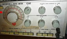
One advantage of this type of poor-man's oscillator is that test frequencies are not limited to a particular instrument (such as the 1kHz models that are typically being used), although the choice of a particular test frequency does imply that a notch filter is available at that frequency. As such, I am about to pull out a circa 1970's boat anchor AWA F240 Distortion and Noise meter, as it includes a very nice twin-T notch filter tuneable from 10Hz to 30kHz.
I don't have an AP style system to investigate this topic, so am running the gauntlet by using just the DUT soundcard itself and a diy passive resistor-divider attenuator, and a passive twin-T notch filter.
With a plain loopback setup, a 1kHz tone with headphone level pot at max can generate a low distortion signal of up to 2.46Vrms (using a software setting up to 943mVrms of a 1V FS level). That 2.46Vrms level does not overload the ADC/input when the input pot is at min, and adjustment of added harmonic levels can suppress loopback harmonic levels to <-130dBr for H2 and <-140dBr for H3.
With a passive -20dB resistor divider attenuator included in the loopback, and with no added harmonics to the 1kHz sinewave, the default 2H level of -115dBr is reduced to -122dBr, and the default 3H level of -103dBr is about the same at -102dBr. It is impractical to attenuate by more than about 20dB as the 2H is starting to approach the noise floor. This result seems to indicate the ADC/input circuitry does contribute some of its own 2H (as 2H dropped by about 7dB) for an input level of 2.46Vrms, however the 3H level had no significant change.
When a notch filter is included in the loopback, the ADC/input is exposed to a much lower fundamental (about 65dB lower than 2.46Vrms) and so loopback measured HD levels likely include a much lower ADC/input contribution. When the nulled harmonic signal was applied to the notch filter, the measured HD levels increased by about 20-30dB to about -110dBr. Readjustment of the added harmonic levels was then needed to supress 2H and 3H levels down to <-140dBr again.
What I see from these tests is that this soundcard is likely to achieve sinewave harmonic distortion levels down at the <-140dBr (<0.00001%) level as a nominal 2.5Vrms test oscillator. Achieving such a low HD level would require a notch filter as a way to suppress ADC/input related distortion from a loopback measurement used to set up the low distortion waveform.
One advantage of this type of poor-man's oscillator is that test frequencies are not limited to a particular instrument (such as the 1kHz models that are typically being used), although the choice of a particular test frequency does imply that a notch filter is available at that frequency. As such, I am about to pull out a circa 1970's boat anchor AWA F240 Distortion and Noise meter, as it includes a very nice twin-T notch filter tuneable from 10Hz to 30kHz.
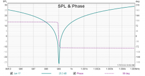
The AWA F240 Distortion and Noise meter allows a custom internal connection direct to the passive twin-T circuit without any circuit alterations. Inserting the notch filter in a simple loopback of an EMU 0404 soundcard, a passive notch to below -110dB can be achieved by first selecting the frequency range (pushbuttons) and adjusting the main dial knob for a minimum (using REW RTA), then the 6 Rejection Balance pots are used in pairs to progressively lower the null level. The first pair of balance knobs marked '>1%' are RV2 and RV5 in the schematic below, and the pairs RV3/RV6 and then RV4/RV7 allow deeper nulling.
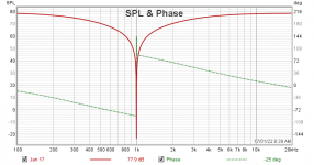
Using RTA with coherent averaging and an FFT of 64k means a commanded 1kHz tone actually generates a sinewave at 999.02Hz, and a spectrum sweep measurement shows that to be the case. The nice aspect of this twin-T tuning configuration is that although there is some slow but measurable drift up in null depth (which can be tweaked back to the same level as the EMU0404 default 2H and 3H harmonics), the exact frequency of the null does not noticeably vary. In contrast, another passive 1kHz notch filter using just fixed (but matched) capacitors and resistors and a trimpot for +/-1Hz fine tuning of the notch frequency only achieved a notch null of circa -85dB, however some slow drift of the notch frequency was noticeable (which is perhaps more problematic).
At 1kHz, this type of notch filter also attenuates the 2H signal by about -9dB and 3H by about -5dB, which needs to be accounted for when assessing actual distortion levels of any DUT added to a measurement loop. The filter is also quite practical out to measuring a 10kHz fundamental as the bandwidth is only down by about -2dB at 80kHz.
Attachments
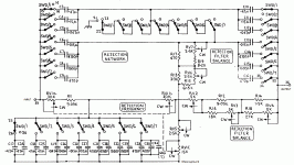
The exact value of the influence on H2, H3 depends on the impendance on both ends of the filter, and is not easy to calculate. To avoid this, I use an active double T filter, with a Q factor of 2.75 and an amplification of 1000x, this way the effect on H2 and above is negligible.
There is also a software project here on diyAudio to null the soundcard distortion. I'll see if I can find it.
Yeh I didn't want to attempt to add an active aspect to the notch filter, as that then introduces some doubt to what distortion it introduces - the F240 does use an active ss amp but I know it incurs significant distortion and noise floor levels (relative to the soundcard performance) - and I only had NE5534 type opamps accessible at the time so just bypassed that issue.
For this particular application the notch is used to suppress distortion introduced by the ADC/input circuitry, and the H2 and H3 type levels were able to be nulled pretty much down in to the noise floor, so I was pleased with the general outcome. Yes HD levels would be up to 8dB higher than reported for H2 (I was running the gauntlet with this setup as I have no independent measurement system of the likes of an AP setup). Having an active notch could well allow the H2 null to be improved by circa 8dB if the null capability was sufficient to use that (and goes to your point about resolution of the REW added harmonic level).
Pano - that would Phoman's effort I think.

the distortion of the built in amp is not significant, even with 1000x amplification: assume a signal of H0 0dB, H2 -120 dB. H0 is attenuted by 80…85 dB and then amplified by 80 dB, so it ends up at ~0…-5 dB. H2 component is amplified by 80 dB and ends up at -40 dB. To prevent the amp generate H2 to interfere with amplified signal H2 a distortion lower than -35 dB is required. That is not too challenging. I have a OPA 228 in it. The limit is likely noise, not distortion.
 That is the topology. This way the filter uses only one amp. R3 must be small, (R1+R2+R3)/(R2+R3) is the amplification, R2/(R2+R3) determines the Q.
Last edited:
You have active feedback to the notch filter (to sharpen the attenuation). Its very similar to the Shibasoku circuit. I discovered that the feedback path to the "T" is quite sensitive. A low impedance drive at very low distortion is required or it will compromise the system. That upgrade produced a significant improvement in the residuals (from below -130 db to more like -150 dB).
If you mean sensitive to pick up hum and noise, i agree. It was necessary to put the whole circuit in a sheet metal housing. If you mean sensitive to the notch depth: in my case the impedance feeding the T-foot is 9 ohm. That seems to be enough to have a >80 dB notch.
I've had time to try a mod on my vintage F240. The twin-T filter has a ground node that is easily changed to an isolated node, which then allows an op-amp based active notch to be implemented, such as in post #7, or using two opamps and unity-gain driving the bottom of the filter as I did. I just tried it with a TL072 and a Q of about 1.2 and trimmed the notch to about -100 to -110dB. That gives me some confidence to try some OPA134 low distortion opamps, for use as a low impedance drive buffer to the notch filter, and for the active notch rejection amp.
AWA did a pretty good job selecting the capacitors in the twin-T network, as most 'C' pairs were well within 1%, although the '2C' were typically a percent or two out (but I'm uncertain if my meter was somewhat an issue). Matching of the C's and R's is critical for better rejection, so I will have a go at padding out the slight capacitance imbalances on all the frequency ranges. The R's are all manually trimmed, so that then leaves the tempco to manage for notch depth stability, which I will try and gauge (with some simple thermal isolation of the instrument). The F240 has 100ppm/C spec resistors, and the tuning pot is 5W WW, so they had tried. The advantage of such vintage test gear is that internals are very well sectioned and shielded, and uses battery power.
AWA did a pretty good job selecting the capacitors in the twin-T network, as most 'C' pairs were well within 1%, although the '2C' were typically a percent or two out (but I'm uncertain if my meter was somewhat an issue). Matching of the C's and R's is critical for better rejection, so I will have a go at padding out the slight capacitance imbalances on all the frequency ranges. The R's are all manually trimmed, so that then leaves the tempco to manage for notch depth stability, which I will try and gauge (with some simple thermal isolation of the instrument). The F240 has 100ppm/C spec resistors, and the tuning pot is 5W WW, so they had tried. The advantage of such vintage test gear is that internals are very well sectioned and shielded, and uses battery power.
- Home
- Design & Build
- Equipment & Tools
- Using a notch filter to assess soundcard ADC and DAC side harmonic distortions