There's some confusion about the G2 rating of this 6P15P. Some data indicates 330V for both anode and G2, while other comments suggests the G2 is "fragile" and should be de-rated, maybe down to 160V like the EL83.
So for those wanting to use this in triode e.g. in a PSE amp, how to proceed? A hefty resistor on G2 or what?
There's a thread on the 6P18P which contains some information but nothing conclusive. Francois G was going to test it but no further info. Maybe he can update?
https://www.diyaudio.com/community/threads/russian-6pi18pi-6-18-any-use.391138/#post-7146682
Based on the Russian datasheet that states limiting values 330V for both anode and g2, I would say you are fine. Taking into account that those are limiting values it would be better to go no further than 300V
Ale Moglia has 6P15P triode-strapped curves:
https://www.bartola.co.uk/valves/2015/05/10/6p15p-triode-strapped-models/
Ale Moglia has 6P15P triode-strapped curves:
https://www.bartola.co.uk/valves/2015/05/10/6p15p-triode-strapped-models/


Typically, in triode connection, g2 can take more volts than its maximum pentode rating. For example, 300 and 400 V for 807; 250 and 400 V for 6146.
If 6P15P is ~equivalent to EL83, then this datasheet might be worth a look: http://www.r-type.org/pdfs/n309.pdf
I have a small stash of NOS Philips PL83 at home, tested a pair in a PP triode outout stage a while ago. Can't remember the exact OP but the plate voltage was somewhere in the neighbourhood of 250V and the plate load was a rather low 5,6k p-p. Worked fairly well thanks to an healthy amount of CFB but lacked power, a couple of watts or so in class A. A fixed G2 voltage (wrt ground) produced a bit more power but the Z prim was still a mismatch for the these tubes.
I have a small stash of NOS Philips PL83 at home, tested a pair in a PP triode outout stage a while ago. Can't remember the exact OP but the plate voltage was somewhere in the neighbourhood of 250V and the plate load was a rather low 5,6k p-p. Worked fairly well thanks to an healthy amount of CFB but lacked power, a couple of watts or so in class A. A fixed G2 voltage (wrt ground) produced a bit more power but the Z prim was still a mismatch for the these tubes.
I run them with 320V as triodes using 220R for screen to plate. No issues in years.
6P15P is not an EL83. We have the original Russian datasheets, I don't know why we keep mentioning the EL83.
But the OP question is about the 6P15P, not SV83. We do have the data for the 6P15P, therefore I do not really understand why is **83 relevant at all.
P.S. I do agree that those "marketing names" only bring confusion to the table. Another one is, for example, Sovtek EL84, which is a 6P14P, not really an EL84.
P.S. I do agree that those "marketing names" only bring confusion to the table. Another one is, for example, Sovtek EL84, which is a 6P14P, not really an EL84.
What I found with the 6P15P at higher screen voltages is when driven hard the screen current can become much higher when the anode voltage drops below 100V than for example a 6BQ5. The result then with a higher screen voltage is very high screen dissipation when the amplifier is driven deep into clipping or loaded with too high a output impedance. Outside of high anode current at lower anode voltages it behaves quite well in 6BQ5 type circuits in my experience. This could explain why some find the 6P15P works just fine while others find it dies from screen failure. The tendency to draw excessive screen current at low anode voltages is associated with pentodes that are "over-suppressed". Having too much G3 suppression does produce a nice linear load line but at the cost of higher screen current at lower anode voltages.
To investigate I tested a 6P15P with various voltage on G3.
With G3 set about +33V above the cathode voltage instead of connected to the cathode a large reduction in screen current at lower anode voltages was noted while still being quite linear with no detectable kink in the anode curves.
To investigate I tested a 6P15P with various voltage on G3.
With G3 set about +33V above the cathode voltage instead of connected to the cathode a large reduction in screen current at lower anode voltages was noted while still being quite linear with no detectable kink in the anode curves.
Last edited:
@Bluesystems
Thanks for posting your testing results. How do you create the +33V bias for the G3? Does it have to be a regulated supply? do you refer it to the cathode voltage?
Just curious.
John
Thanks for posting your testing results. How do you create the +33V bias for the G3? Does it have to be a regulated supply? do you refer it to the cathode voltage?
Just curious.
John
If I understand correctly, you are referring to 6P15P in pentode service, when due to PP transformer action the anode voltage swings below the screen (G2), kept (near) constant by the separate screen supply. Does that mean there would be less of a problem in this regard when using the 6P15P with an UL output transformer?What I found with the 6P15P at higher screen voltages is when driven hard the screen current can become much higher when the anode voltage drops below 100V than for example a 6BQ5. The result then with a higher screen voltage is very high screen dissipation when the amplifier is driven deep into clipping or loaded with too high a output impedance.
Could you elaborate on pentodes that are over-suppressed?The tendency to draw excessive screen current at low anode voltages is associated with pentodes that are "over-suppressed". Having too much G3 suppression does produce a nice linear load line but at the cost of higher screen current at lower anode voltages.
To investigate I tested a 6P15P with various voltage on G3.
Could you list the full data on the operating points that you found particularly good?
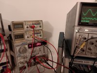
I used a utracer3+ to measure the 6P15P plate and screen current curves with a added bench supply to allow a small dc voltage to be varied on G3.
What I found was with about 28~33V volts added between the cathode and G3 the screen current levels on the 6P15P reduced close to or a bit less than a NOS 6BQ5 under about the same conditions of plate, screen and G1 voltage.
I used a screen voltage of 250V in testing with the utracer3+ as this is around where the screen drops to with UL operation and also what I set the screen regulator voltage to in my design that is straight pentode operation.
Unfortunately I seemed to have been a bit sloppy in keeping track of all the generated data files or I would post them. Perhaps I will consider to remeasure if it is of interest.
In the actual amplifier I built I used a small zener bypassed by a capacitor between the cathode and G3 pulled up by a few mA from a resistor from the B+ supply.
The reference on pentode suppression was a interesting posting I found on the web at "http://www.r-type.org/articles/art-004c.htm#003"
By varying the cathode to G3 voltage with pentodes I have that feature a separate connection for G3 the results seem to confirm what the author states.
I found it quite interesting.
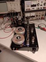
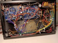
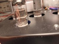
Here is a picture of the resulting amplifier. It provide a pleasant sound with modest power around 12 to 14 watts.
Distortion is well below 0.05% before clipping. The toroidal output transformers work extremely well down to 20HZ providing full power with the same low distortion as at 1KHz. I however was not so happy with the interwinding capacitance of the toroidal transformers as the 20Khz power level is down about 3dB from 1KHz as the 6P15P runs out of plate current trying to drive the transformer capacitance. First time I have tried toroidal output transformers and overall I think I prefer a conventional laminated type.
What I found was with about 28~33V volts added between the cathode and G3 the screen current levels on the 6P15P reduced close to or a bit less than a NOS 6BQ5 under about the same conditions of plate, screen and G1 voltage.
I used a screen voltage of 250V in testing with the utracer3+ as this is around where the screen drops to with UL operation and also what I set the screen regulator voltage to in my design that is straight pentode operation.
Unfortunately I seemed to have been a bit sloppy in keeping track of all the generated data files or I would post them. Perhaps I will consider to remeasure if it is of interest.
In the actual amplifier I built I used a small zener bypassed by a capacitor between the cathode and G3 pulled up by a few mA from a resistor from the B+ supply.
The reference on pentode suppression was a interesting posting I found on the web at "http://www.r-type.org/articles/art-004c.htm#003"
By varying the cathode to G3 voltage with pentodes I have that feature a separate connection for G3 the results seem to confirm what the author states.
I found it quite interesting.
Here is a picture of the resulting amplifier. It provide a pleasant sound with modest power around 12 to 14 watts.
Distortion is well below 0.05% before clipping. The toroidal output transformers work extremely well down to 20HZ providing full power with the same low distortion as at 1KHz. I however was not so happy with the interwinding capacitance of the toroidal transformers as the 20Khz power level is down about 3dB from 1KHz as the 6P15P runs out of plate current trying to drive the transformer capacitance. First time I have tried toroidal output transformers and overall I think I prefer a conventional laminated type.
Attachments
Last edited:
Many thanks for the detailed explanation! The toroidals you are using as OPTs are 115+115V to 6V designed for mains (50/60Hz) operation? In my experience these do indeed not reach 20kHz, mine were down by about 2dB, triode Output tubes and no GNF. Next test will use the secondaries as cathode feedback, I think that could push HF a bit up.
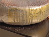
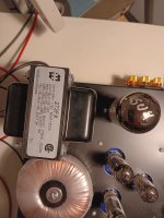
The toroidals are AnTek, model MP-10W80 sold for tube output stages, 8K P-P and rated at 10 watts.
Not sure they are much different in internal construction other than the winding values from the power transformer versions but I have not wanted to cut one open to see how they are made inside. The 10 watt rating seems very conservative as I see well over 10 watts of clean power at 20Hz from this unit PROVIDED the output tubes as well matched and the bias current is matched perfectly (to 1mA or better) in the output pair. Distortion in these transformers rises quickly as the output bias current match between output pairs becomes less accurate. As I said I found the 20KHz performance less than hoped for due to increased current loading of the output tube plates.
Not sure they are much different in internal construction other than the winding values from the power transformer versions but I have not wanted to cut one open to see how they are made inside. The 10 watt rating seems very conservative as I see well over 10 watts of clean power at 20Hz from this unit PROVIDED the output tubes as well matched and the bias current is matched perfectly (to 1mA or better) in the output pair. Distortion in these transformers rises quickly as the output bias current match between output pairs becomes less accurate. As I said I found the 20KHz performance less than hoped for due to increased current loading of the output tube plates.
An auto bias board might be useful for a toroid OPT to keep the bias stable and matched over the life of the tubes. I have used a couple versions from Erhard Audio and they work very well.
Today I remeasured the 6P15P tube's screen current while varying the voltage on G3 vs a older RCA NOS 6BQ5 I have on hand I keep as a reference as to how tubes really were once upon a time.
The quick summery is yes in fact the screen current in a 6P15P with G3 connected to the cathode is much higher than the screen current in a 6BQ5 under the same operating conditions.
Reducing the 6P15P screen power margin more is the power rating of the 6P15P screen is lower at 1.5 watts Vs the 6BQ5 at 2watts (4W peak). Admittedly comparing Russian data sheets to Western data sheets does seem like apples to oranges but this is what I have in information.
So with higher screen currents and lower rated screen power in the 6P15P it is not hard to imagine some failures may occur when used in 6BQ5 circuits.
Looking at the attached anode and screen current curves for a 6BQ5 and a 6P15P with three G3 voltages 0V, +28V, and -10V, it can be seen the pentode suppression levels are quite different on a 6P15P with G3 connected to the cathode (G3=0V) compared to a 6BQ5.
My guess is the 6P15P was optimized for linearity and the 6BQ5 was for power output.
Having G3 pined out separately is a bonus on the 6P15P allowing the tube to be tuned for linearity vs power output.
A 6P15P with 0V from cathode to G3 shows a loss in peak anode current at lower voltages and a rise in screen current compared to the 6BQ5 showing the 6P15P is a over suppressed pentode.
Compare the curves between the 6BQ5 and a 6P15P with 28V from cathode to G3 the anode. Adding a small positive voltage to G3 has the effect of making it a less effective suppressor. Go too far in voltage and G3 starts to attract far too may electrons away from the plate creating problems again.
With 28V on G3 the 6P15P anode current has now increased and the and screen current decreased to levels are at their closest match between a 6BQ5 and a 6P15P.
Going one step further to show the continuum that pentode suppression is compare the 6P15P with -10V on G3 relative to the cathode and a 6BQ5. The -10V makes the G3 suppressor grid more effective. This curve now shows a large loss in anode current at low voltages and a steep rise is screen current showing a very over suppressed pentode.
In my amplifier design I set G3 for each output pair at +28V by a 1N5255B zener bypassed by a 47uF capacitor connected between the output pair cathodes and G3 with G3 pulled up by a 39K resistor connected to B+. It is important that the zener and capacitor negative end is connected to the cathodes of the 6P15P output pair NOT to ground in the case of self bias. Testing showed it is important the G3 impedance to cathode be kept low thus the zener and capacitor over a simple resistor divider.
With this setup I found the 6P15P happily tolerates 350V on the anodes with 250V on the screens. I used a regulated screen supply with split fixed/self bias for operating point stability. As I use my design amplifier for HiFi I have no idea how well this would work out for a musical instrument amplifier.
Attachments

Last edited:
The toroidals are AnTek
Menno van der Veen toroids are good for audio with bandwith over 70 kHz - this is info from my serviceman & custom builder of tube amps.
I was at his workshop to take my EL84 PP amp when he showed me his 6SL7-EL84 PP paralleled amp. We listened it and talked and he was very satisfied with outputs and made that comment. I believe him when he says such things since the guy has a lot of measuring equipment and use it much.
Local company named Trafco makes them under licence. There was ( is ? ) some other comp. in Eu making them also.
@Bluesystems,In my amplifier design I set G3 for each output pair at +28V by a 1N5255B zener bypassed by a 47uF capacitor connected between the output pair cathodes and G3 with G3 pulled up by a 39K resistor connected to B+. It is important that the zener and capacitor negative end is connected to the cathodes of the 6P15P
Would you kindly show a schematic of how you implemented this? Thanks for this good information. How is the amplifier working out in the month since you wrote this.
Thanks for your interest.
Overall I am very happy with the results.
I switched from fixed bias in pentode to UL mode to lower the THD and improve the high frequency performance and went with a hybrid bias design to provide some over drive protection for the 6P15P output tubes.
This did cost some power output it now producing about 10.5 watts in UL , hybrid bias mode. It is enough for my use.
THD at one watt is very low at 0.0158% and rises just before clipping at 10.5 watts to 0.2%
The 6P15P seem completely happy in UL mode with 337V on the screens.
I have set G3 to about 28V above the cathode to limit the screen current (and screen power!) at full out power as otherwise the 6P15P screen current rises to high levels when the plate drops below about 100 volts.
The PCB incorporates a built in high voltage regulator for the low level section providing a totally stable and clean rail.
Perhaps over kill but for me a high regulator is a acceptable added complexity to eliminate concerns about power supply rejection ratio concerns.
The driver stage is a balanced cascode using a BJT and provided with a current source on the cathodes.
This driver stage produces a lot of gain that is low in distortion.
The driver stage output impedance is a bit on the high side for ideal high frequency performance but it kept the parts count down for a fully balanced design.
Fortunately the 6P15P is about as easy to drive as a 6BQ5 and can be quite linear and giving the driver stage a easy time.
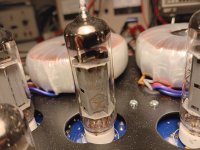
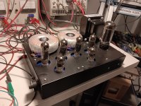
I have attached pictures of the last version I settled on.
This was my first designed from scratch push pull tube amplifier and I learned a lot during this project. Great fun!
I hope you find this of interest.
Overall I am very happy with the results.
I switched from fixed bias in pentode to UL mode to lower the THD and improve the high frequency performance and went with a hybrid bias design to provide some over drive protection for the 6P15P output tubes.
This did cost some power output it now producing about 10.5 watts in UL , hybrid bias mode. It is enough for my use.
THD at one watt is very low at 0.0158% and rises just before clipping at 10.5 watts to 0.2%
The 6P15P seem completely happy in UL mode with 337V on the screens.
I have set G3 to about 28V above the cathode to limit the screen current (and screen power!) at full out power as otherwise the 6P15P screen current rises to high levels when the plate drops below about 100 volts.
The PCB incorporates a built in high voltage regulator for the low level section providing a totally stable and clean rail.
Perhaps over kill but for me a high regulator is a acceptable added complexity to eliminate concerns about power supply rejection ratio concerns.
The driver stage is a balanced cascode using a BJT and provided with a current source on the cathodes.
This driver stage produces a lot of gain that is low in distortion.
The driver stage output impedance is a bit on the high side for ideal high frequency performance but it kept the parts count down for a fully balanced design.
Fortunately the 6P15P is about as easy to drive as a 6BQ5 and can be quite linear and giving the driver stage a easy time.
I have attached pictures of the last version I settled on.
This was my first designed from scratch push pull tube amplifier and I learned a lot during this project. Great fun!
I hope you find this of interest.
Attachments
-
 THD at 1 watt.jpg313.1 KB · Views: 57
 -
 20241122_195306.jpg544.2 KB · Views: 60
 -
 20241122_195149.jpg288.7 KB · Views: 54
 -
 20241122_195108.jpg241.1 KB · Views: 55
 -
 20241122_195034.jpg268.1 KB · Views: 59
 -
 20241122_195015.jpg289.9 KB · Views: 63
 -
 20241122_194954.jpg377.7 KB · Views: 64
 -
3186AB10-POWER-SUPPLY.PDF18.9 KB · Views: 50
-
3186AB10-6P15P-6N1P.PDF29.5 KB · Views: 80
-
 THD at 10.5 watts.jpg284.3 KB · Views: 57
- Home
- Amplifiers
- Tubes / Valves
- Using 6P15P in triode at 300V - suggestions?