I purchased one of the JC-2 "clone" kits off Ebay. It came with matched 2SK246/J103's for the input FET's.
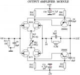
Attached below is the schematic of the circuit.
I also have some matched 2SK170/J74BL devices that I would like to try in place of the K246/J103 combo.
Will I need to change the value(s) of any resistors in order to use them?
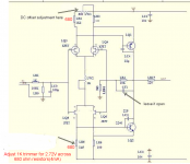
The instructions state to adjust the 1K ohm trimmers until you get a voltage drop of 2.5-3V across the 1.5K ohm resistors.
Would this also apply to using the K170/J74BL combination?
Two milliamps(3V across 1.5K ohm) doesn't sound like much current to me.😕
Thank you...
Attached below is the schematic of the circuit.
I also have some matched 2SK170/J74BL devices that I would like to try in place of the K246/J103 combo.
Will I need to change the value(s) of any resistors in order to use them?
The instructions state to adjust the 1K ohm trimmers until you get a voltage drop of 2.5-3V across the 1.5K ohm resistors.
Would this also apply to using the K170/J74BL combination?
Two milliamps(3V across 1.5K ohm) doesn't sound like much current to me.😕
Thank you...
Attachments

2ma was ued by Borbely in the jfet differential input of his preamp, Dac, and power amp. It's fine
Thanks ticknpop.
That answers one of my questions, but I still need to know if any resistors need to be changed if I use the K170/J74's.
That answers one of my questions, but I still need to know if any resistors need to be changed if I use the K170/J74's.
one reason for silence might be there is at least one other thread where this circuit and your proposed change was commented on by the original designer.
borbely wrote a couple of articles on designing with jfets that would be very useful info to you also.
regards,
mlloyd1
borbely wrote a couple of articles on designing with jfets that would be very useful info to you also.
regards,
mlloyd1

Best to use the Linear Systems devices sold in the DiyAudio store.
Alleged Toshibas are usually forgeries and do not meet specs.
fyi.
_-_-bear
ps. hi John...
Alleged Toshibas are usually forgeries and do not meet specs.
fyi.
_-_-bear
ps. hi John...
Thanks Bear for the advice.
The K170/J74BL's I have are indeed genuine and were verified by another member who tested them with curve a tracer.
Some I purchased from fetaudio.com.
The K170/J74BL's I have are indeed genuine and were verified by another member who tested them with curve a tracer.
Some I purchased from fetaudio.com.
Ammel68
Try to locate PDF with EB-604\410 Borbely starter kits part 1
Read it and you will fine the answer to your question
Try to locate PDF with EB-604\410 Borbely starter kits part 1
Read it and you will fine the answer to your question
Ammel68
Try to locate PDF with EB-604\410 Borbely starter kits part 1
Read it and you will fine the answer to your question
Is this what you're referring to?
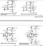
http://www.pearl-hifi.com/06_Lit_Archive/14_Books_Tech_Papers/Borbely_Erno/Borbely_on_Line_Amps^.pdf
First off, Borbely is using 24V supplies where I'm using 15V supplies. Not sure how much that will change things.
I see where he states running his first stage at 2mA just as ticknpop stated in post 2.
So I'm assuming 2mA is going to work using K170/J74's, though I read on another JC-2 thread where John Curl stated that running them at 6mA will sound better.
None of the circuits from the Borbely PDF below look identical to the circuit I posted initially, though the first half of figure 5 looks very similar.
Attachments
The actual input stage current is not very important. What is important is the Idss of the input jfets. IF they are 10ma or more, then 6ma or so is better. If they are 5ma (Idss) or less, then 2 ma is better. This design is over 40 years old and was first used at +/-24V as a line driver for the Greatful Dead 'Wall of sound' starting in 1973. Later, in 1974, a 15V version was made for the Levinson JC-2 line stage.
Thank you for clarifying that point, Mr. Curl.
Most of the matched K170/J74BL JFET's I have are around 7-7.5mA Idss.
From what I understand, trying to find K170/J74BL in 10mA or higher Idss is literally like "trying to find a needle in a haystack".🙂
Most of the matched K170/J74BL JFET's I have are around 7-7.5mA Idss.
From what I understand, trying to find K170/J74BL in 10mA or higher Idss is literally like "trying to find a needle in a haystack".🙂
You could move the Id to 4ma without any problem. Just halve the value of the input stage load resistor.
- Status
- Not open for further replies.
- Home
- Source & Line
- Analog Line Level
- Using 2SK170/J74BL in Ebay JC-2 "Clone"