I received this inquiry in a Private Message; it seemed to me that the collective wisdom of ALL diyAudio members would probably give a better answer than any one person could. Here is their question, please be kind:
I haven't mentioned the requester's name; he can identify himself here, or not, as he sees fit.
Would anyone like to offer some answers or opinions?
That's all I know. I wish I knew whether the question writer imagined his two coils to be wound on the same core, possibly implementing a common mode choke. But I don't know that.I want to know few elementary things, if possible please do clear my doubts. I am stuck in my power supply project.
I dont understand electronics in detail but I am aware of the oscillations created when diodes switch on and off. I also know that inductors can be created to cutoff at certain frequencies. So question is can I put two inductors of around 2.5mH (coil wound on a silicon steel core) across the + and - rails of a bridge rectifier to remove the oscillations. Will it snub the oscillations ?
Thank you.
I haven't mentioned the requester's name; he can identify himself here, or not, as he sees fit.
Would anyone like to offer some answers or opinions?
How can it snub anything when at HF it is high impedance. That's why you use capacitors in this position.
More craziness from ginetto61!
More craziness from ginetto61!
Hi,
Standard practice is small capacitors across the legs of the rectifier.
Nearer the rectifier the better, to cut down on any generated RFI.
Inductors won't help at all, and suggesting 2.5mH across the rails
suggests a fundamental misunderstanding of all the basic theory,
and no idea of the extremely serious consequences of doing that.
rgds, sreten.
Last edited:
bang fiz zwhut?!? will be the outcome.
Pick a suitable soft-recovery rectifier if you must - there are many!* - and the whole issue goes away entirely.
* me, I like the Qspeed parts from experience. V V robust, and cheap enough; and meets specs.
Pick a suitable soft-recovery rectifier if you must - there are many!* - and the whole issue goes away entirely.
* me, I like the Qspeed parts from experience. V V robust, and cheap enough; and meets specs.
The diodes do not create oscillations. They excite an existing oscillatory circuit formed by stray capacitance and inductance in the circuit.
Inductors cannot be created to cutoff at certain frequencies. Filters can do that, and filters can be made using inductors and capacitors.
A bridge rectifier does not have rails. It does have DC outputs. Putting an inductor across these outputs will result in a short circuit, and then you just have to wait to see which blows first: the inductor, the diodes, the transformer or the fuse.
Snubbing oscillations is generally done using capacitors, in conjunction with resistance (which may or may not already be present in the circuit e.g. transformer resistance).
The original questioner is trying to run before he can walk. We have all done that, when we were first learning electronics. We hear of a problem and come up with a solution; we don't realise that we have misunderstood the problem and the solution, and in any case we should not worry about that problem as it is still several years ahead of where we are now.
My advice would be to build and understand simple PSUs for undemanding applications. Debug them. Do lots of reading. Buy an oscilloscope and learn how to use it. Then one day you can build a really good PSU for a demanding application.
Inductors won't help at all
Inductors will help if there is sudden changes to load, in the form of pulses.
All PC motherboards are loaded with several Inductors because load can rapidly change from 50~700W.
Audio circuitry power supply is not that demanding, load changes are tremendously slow compared to what pulses can do.
For people with some advanced understanding regarding electrical measurements, I will say that in electric motors there is regular current measurement, and inrush current measurement.
In electronics those Inductors dealing exclusively with inrush current management.
The selection of Inductors is a choice of true electronics engineers, which they do have complete understanding regarding needed requirements of their specific circuitry.
They would have to be wired in series with the load though, not what the original question was.
Oops, now another dilemma put into Ginetto's head
Oops, now another dilemma put into Ginetto's head
Thank you DF96! I hope the original requester pays careful attention to your advice and suggestions.
Respected diyaudio members, that message was sent to Mr. Mark Johnson by me.
Wait a moment please...
Wait a moment please...
AND OH MY GOD I MADE A FUNDAMENTAL MISTAKE ! "across the rails" means short circuit !!!!!Sorry.
I was reading this at that time:
http://www.diyaudio.com/forums/power-supplies/190638-rc-snubbers-diode-recovery-noise-4.html
.......and I saw that Mr. Mark Johnson was online and thought of getting a quick reply. I dont remember the time exactly but I guessed it was late night in USA so I hurried. I waited for some time but got no reply and I logged off. Only now I am seeing this. Sorry for being unscrupulous.
And the kind responses of the members here have made it clear to me that there are other fundamental mistakes too. Thank you for your replies. I am actually a mechanical engineer. I have taken up a couple of projects to "retrain" my brain after I suffered a bout of major depression. One is this project and the other is creating a table saw from scratch which has made some decent progress. Powersupply project is stuck because I still am reading and misunderstanding and understanding. I have been doing some hobby stuff since some years and hence my hollow bravado.
DF96: "The original questioner is trying to run before he can walk."
I agree a 1000%.
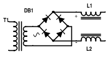
What I meant was this:
A 2.5mH coil connected to + of bridge rectifier and another similar coil connected to the - of the bridge rectifier. Not a CM choke(Although I am thinking of it now).
Please see attached image.
I was reading this at that time:
http://www.diyaudio.com/forums/power-supplies/190638-rc-snubbers-diode-recovery-noise-4.html
.......and I saw that Mr. Mark Johnson was online and thought of getting a quick reply. I dont remember the time exactly but I guessed it was late night in USA so I hurried. I waited for some time but got no reply and I logged off. Only now I am seeing this. Sorry for being unscrupulous.
And the kind responses of the members here have made it clear to me that there are other fundamental mistakes too. Thank you for your replies. I am actually a mechanical engineer. I have taken up a couple of projects to "retrain" my brain after I suffered a bout of major depression. One is this project and the other is creating a table saw from scratch which has made some decent progress. Powersupply project is stuck because I still am reading and misunderstanding and understanding. I have been doing some hobby stuff since some years and hence my hollow bravado.
DF96: "The original questioner is trying to run before he can walk."
I agree a 1000%.
What I meant was this:
A 2.5mH coil connected to + of bridge rectifier and another similar coil connected to the - of the bridge rectifier. Not a CM choke(Although I am thinking of it now).
Please see attached image.
Attachments
My curiosity started after reading on this forum about the nice improvement in sound after the ringing was "snubbed". I too wanted it 🙂
I also came across this :
http://eclipsedt.com/2011/02/multip...ications-in-an-instrument-grade-power-supply/
There was another video on Youtube which showed the frequency sweep done thru an inductor and response displayed on an oscilloscope. I am not finding the video now. I forgot the key words.
I also arrived at the 2.5mH value after plugging in values here:
http://www.electronics2000.co.uk/calc/reactance-calculator.php
So at 2.5mH inductance a signal of frequency > 50Hz will encounter resistance. Higher the frequency greater the resistance. I DID NOT KNOW THAT A CAPACITOR "HAS" TO BE USED TO MAKE A FILTER. I thought an inductor was enough.
As you can see my understanding is half baked ! 🙁
Last edited:
bang fiz zwhut?!? will be the outcome.
Pick a suitable soft-recovery rectifier if you must - there are many!* - and the whole issue goes away entirely.
* me, I like the Qspeed parts from experience. V V robust, and cheap enough; and meets specs.
Its not only about diode ringing.
A filter can suppress LM317 noise isnt it. I have bunch of LM317 coming down the path. Hence my craving for a filter.
The diodes do not create oscillations. They excite an existing oscillatory circuit formed by stray capacitance and inductance in the circuit.
Inductors cannot be created to cutoff at certain frequencies. Filters can do that, and filters can be made using inductors and capacitors.
A bridge rectifier does not have rails. It does have DC outputs. Putting an inductor across these outputs will result in a short circuit, and then you just have to wait to see which blows first: the inductor, the diodes, the transformer or the fuse.
Thank you for your reply.
I had read about the transformer creating those oscillations on this forum. I didnt understand the concept but I understood the Tx is the culprit.
Please do tell me how to determine the L and C values in a CLC filter. 🙂
I will forego the inductors idea and finish my project as shown below. There is still a long way to go before I understand it. But I will keep posting questions/starting threads to understand basic concepts. I hope I get helped.
Tx >> Bridge rectifier >> capacitor bank >> Voltage reg >> current limiter >> output
Thank you.
Tx >> Bridge rectifier >> capacitor bank >> Voltage reg >> current limiter >> output
Thank you.
Read Horowitz and Hill - a new edition has just come out. That will answer most of your questions.
Until you understand things, build kits.
Until you understand things, build kits.
confusion of the purpose perhaps. There is PS filtering at which inductors in conjunction with caps and resistors filter to DC......but diode switching noise should be damped at the source in order to reduce the sudden di/dt of the change in input current to the PS caps, harmonics of which may pass through the PS filter. Some types of rectifiers are better at higher (SMPS) frequencies but others are more suitable for mains frequency. Pros and cons of any device application.🙄 Most of the time at mains frequency, 100nf + 10R across each diode in the bridge is sufficient to dampen switching noise.
Quite proper advice . Well doneRead Horowitz and Hill - a new edition has just come out. That will answer most of your questions.
Until you understand things, build kits.
I have opened up a few smps to see whether I had the skills to work on them.
What was very clear to me was that all of them were riddled with snubbing resistors. Everywhere !
I tried counting PC type smps and I got to about 18 snubbers inside that one unit.
If the professional penny pinchers reckon they need that many, then I believe we need that many !
What was very clear to me was that all of them were riddled with snubbing resistors. Everywhere !
I tried counting PC type smps and I got to about 18 snubbers inside that one unit.
If the professional penny pinchers reckon they need that many, then I believe we need that many !
- Status
- Not open for further replies.
- Home
- Amplifiers
- Power Supplies
- Use inductors to prevent diode-caused oscillation?