Is this advisable? I want to do this (novelty mostly) as the base stoppers in an amp project. I found a trace resistance calculator that will give the resistance for a given length, width and copper thickness.
I have seen this somewhere else, on a board somewhere and I thought I'd pose the question.
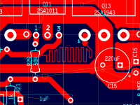
An example of what I'm thinking:
I have seen this somewhere else, on a board somewhere and I thought I'd pose the question.
An example of what I'm thinking:
Attachments
Yes it works. Traces have also been used to create capacitors and inductors.
Three disadvantages:
Heat dissipation is limited, which may or may not be important. It depends on the current that will be present, so use as an emitter resistor on a the output devices of a power amp is likely a non-starter!
It may be hard to control the process. The importance of this depends on how critical the value and consistency of the value are. With large production volumes and lots of money these can be overcome.
If will be messy to change values if the need arises.
The biggest problem is the absolutely hopeless tolerance involved for practical PCB fabrication.
A real example: assume that you are happy to have a resistive trace that is 0.5 inch long and use 1/2 oz copper.
A 4 mil wide trace will give you 0.12 ohms.
The problems are:
1. You will NOT be able to make this at home
2. You will be seriously limited in your choice of a fabrication house
3. If you find a fabrication house to manufacture your pcb, then the width accuracy will be +/- 1mil typically. This is +/- 25% tolerance for the width alone.
4. The plating thickness will vary, typically +/-10%
5. It will consume more PCB real estate than a comparable discrete resistor (the resistor needs just two pads)
So you have a 0.12 ohm resistor that must be manufactured by a specialist PCB fabricator that will have an approximate tolerance of +/-35%.
If you really want to get depressed... check out the temperature coefficient of copper.
Note: the calculations get worse if you use 1oz copper which is likely for a power amplifier.
Conclusion: use regular 0.5W 1% metal film resistor!
Traces have also been used to create capacitors and inductors
MJL21193;
A big problem using the track example you have attached is infact what sam9 told in the quote above.....
The track will act both as a resistor, a capacitor and an inductor. You can get in serious trouble if you don't presicely calculate the capacistance and induction for such "resistor" track. You end up with what's equal to a wirewound resistor with a small cap in parallel !!!! This can cause both stabillity problems and cause very bad high frequency reproduction.
You can make it, but you have to do some practical tests and measurements to uncover all problems mentioned above.
All gave good points already; I want just to remember once more that most board houses do only 8mills (and larger) so the possible resistance is pretty tiny; for sure much too small for gate stoppers.
IMHO a more usefull trick is to use traces/fills for small capacitors, say a few pFs. But that's already for the well trained people 😉
Have fun, Hannes
IMHO a more usefull trick is to use traces/fills for small capacitors, say a few pFs. But that's already for the well trained people 😉
Have fun, Hannes
acd is right. the trace you show is used more often as an inductor or in digital circuits as a delay line since it's actually several lumped inductance and capacitance elements (also known as a lossy transmission line). you may find that the delay provided doesn't affect your phase margin much, but who wants to take chances? use a resistor. it may cost a few extra cents on the front end, but save the cost of smoked components and redesign on the back end.
John,
The layout you describe makes it non inductive since the magnetic fields cancel, also parasitic capacitance is in series and effect is minimal.
Stray pick-up is minimized due to the "windings" mirroring and often used in RF amplifier stages. The value could easily be trimmed by inserting a few cob-web like tracks that can be cut or solder blobbed to tweak the value almost exactly.
Nico
You can get tighter tolerances than VivaVee mentions but you have to pay for it. On top of that there will be a nice NRE charge.
I think the bottom line is that the technique is used as a last resort when there is no way to get the required value or to get it at a particular location.
I think the bottom line is that the technique is used as a last resort when there is no way to get the required value or to get it at a particular location.
Thank you all for the responses. I can see the impracticality of it now.
Besides, the amp I'm working on doesn't need base stoppers, so no need for this now.
Besides, the amp I'm working on doesn't need base stoppers, so no need for this now.
Look at a computer motherboard..it must work, they do it a lot wobbly traces are the least of their problems.
neutron7 said:Look at a computer motherboard..
5 or more layers too.
The equivalent of a small classA amp smack dab in the middle too with a heatsink/fan on top. 🙂
I had an ulterior motive for this thread. I'll share that later maybe...
Neutron7 said
Look at a computer motherboard..it must work, they do it a lot wobbly traces are the least of their problems.
I think you will find that the wobbly traces are used to adjust clock skew rather being used as resistors.
And sam9 is right. You can get better tolerances than I mentioned above. But not for the kind of money that would make you NOT use a conventional resistor.
neutron7 said:Look at a computer motherboard..it must work, they do it a lot wobbly traces are the least of their problems.
The wobbly traces on motherboards are usually the data buses. When you are running at the speeds that modern motherboards are then you need to match the length of the track on each of the data lines to avoid propogation delay problems .
Just imagine that the signals are cars travelling at the same speed. If the road (track) is shorter than one car will arrive at the end of the road before the other. And in high speed digital circuits thats not a good thing.
Kev
This is why I suggest keeping a roll of small gage Manganin wire around. Whenever you need an odd and small value of resistance, just measure it out, double it over as needed, and solder it in. Constantan also works well and is more available, but has a higher voltage coefficient with copper.
Hi MJL21193,
Digikey will ship in one day where you are. 😉
All very good points brought up too. However, the exact resistance is not important as a base stopper. So trace thickness is the greatest variable, the rest of the dimensions are easy to keep accurate. A resistor still works the best. Watch the tempcos on resistors though!
-Chris
anatech said:Hi MJL21193,
Digikey will ship in one day where you are. 😉
All very good points brought up too. However, the exact resistance is not important as a base stopper. So trace thickness is the greatest variable, the rest of the dimensions are easy to keep accurate. A resistor still works the best. Watch the tempcos on resistors though!
-Chris
Hi Chris,
I just received an order from Digikey on Friday. 🙂
They have resistors lower than 10 ohms, but not is small amounts. I don't need 10000 pieces.
It's in the breeze anyway, as the amp I'm working on doesn't need base stoppers. Project is here.
It was more of a novelty anyway. I have 10R resistors, I could just parallel a couple or more. Takes up space, but not much.
Conrad's Manganin wire sounds interesting though.
Hi,
Yes, Manganin wire has been a popular low value resistance material for ages. They used to recommend it in R-E (Radio Electronics) projects often enough. Some of those materials need to be crimped as they don't solder easily I think. Also, peer inside a toaster. There is a fair amount of resistance wire in there. I do believe you do need to crimp that stuff. Your application was not that critical was it? Not requiring an exact and constant resistance?
Now, for smaller quantities ... Buy four terminal resistors. They are normally sold by singles. Newark is another good rock to peer under.
I noticed you didn't have amps to compare your creation with. I'll offer my living room to you. Victims are a pair of PSB Stratus Gold (older model) speakers, 4 ohm nominal. Comparison amplifiers are the new Cyrus Mono X amps and an older Marantz 300DC. Those are both pretty good amplifiers and are rated around 150 WPC into 8 ohm loads. Also, there is a dedicated AC circuit on the same phase as the utility outlet the house came with. I only have 14 GA wire running to the speakers at the moment. A fine strand 12 GA has not been available yet, not reasonably priced stuff.
-Chris
anatech said:I'll offer my living room to you.
Hi Chris,
You are a true gentleman. 🙂
When I get a stereo pair done and have the chassis in a reasonable state of completeness I'll take you up on your offer.
I know what sounds right and what doesn't but my ears aren't what they used to be. I'll count on yours to judge the sonic merits.
In any case, I'm listening right now (in mono). Using my regulated lab supply for the power supply, it sounds pretty fracking good.
PCB track resistors only make sense for current sensing and very low values under 0.1 ohms. On the other hand, there are PCB mount shunts for that purpose too.
Hi John,
No problem. As a few others know, I am serious about the offer and glad to help. It will be a pleasure. My bench is also at your disposal if needed, just in case you want to change something. Now, getting to said bench may be a challenge.
About ears. At 49, I can't say my hearing is as good as it used to be. You will be the judge of that. I do understand that you don't want to judge your own work. That is very hard to do.
Hi Eva,
Just crack open a few dead Fluke meters. They use pretty good shunts. Many are Kelvin types.
-Chris
- Status
- Not open for further replies.
- Home
- Amplifiers
- Solid State
- Use board trace as a low value "resistor"