Hey guys,
I have a prosumer daw card here (a focusrite) which uses a CS42428 codec (http://www.cirrus.com/en/pubs/proDatasheet/CS42428_F1.pdf), and I would like to try to optimize the post-dac components for quality.
At present, the output from the dac goes to a JRC 4565 op amp. I have a feeling the JRC is a cheap component, and that perhaps a replacement along with either replaced or eliminated output capacitors might be an interesting upgrade.
Alternatively, I would be interested in bypassing the op amp completely and simply using the direct output from the dac though I am guessing there are going to be some issues (particular with regards to impedance and SNR). Anybody try this approach?
What would be a standard sort of mod for this sort of situation? Being that the 4565 seems to be a relatively common component, are there known drop-in replacements for it?
I'm approaching this with an open mind and have no preferences, so any recommendations or thoughts on the matter would be greatly appreciated. Thanks! 🙂
no ideas? If I provided a small schematic of the output stage could someone give me some tips on what I could do with it? Thanks.
Maybe someone can help me with this:
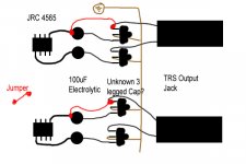
The coupling cap for the opamp is 100uF electrolytic , followed by what appears to be a small 3 legged cap of unknown size. I can't make out what it says on the side, but it is small and orange/pinkish and is sort of shaped like an upside down version of this:
v\/v
I am presently using a jumper to bypass the coupling cap and whatever else that other thing is on one of the differential pairs on each channel. One side of each signal (of the differential output) has a good bit of DC, but the other doesn't seem to have any so I have the jumper on the the side of the signal with no dc and simply connect them. The output no longer measures and DC. I've done a quick signal check and there doesn't seem to be any detriment.
Any suggestions for the optimal output? Thanks to anyone who helps 😀
Attachments
Since its a voltage output DAC, you have choices.
My first Idea is a 10K 1:1 transformer, with or without a load resistor.
Second thought, a Broskie Cathode Follower, if Tubes float your boat. http://tubecad.com/Product_PDFs/BCF 9-Pin.pdf
While I couldn't tell you how, a discrete FET version should be straightforward.
Just Random thoughts.
Doug
My first Idea is a 10K 1:1 transformer, with or without a load resistor.
Second thought, a Broskie Cathode Follower, if Tubes float your boat. http://tubecad.com/Product_PDFs/BCF 9-Pin.pdf
While I couldn't tell you how, a discrete FET version should be straightforward.
Just Random thoughts.
Doug
thanks for the reply Doug,
How large would such a transformer be? I don't have much room to work with in the enclosure, and I'm guessing snaking the wire a few inches and mounting the transformers outside the case wouldn't be such a good idea.
I am thinking back and the 4565 might be SMD which is beyond what tools I presently have. Any sort of attempt to preempt the 4565 would require me to cut the traces just past the dac, and then jump the dac output to either new transformers or some sort of external preamp is that correct?
If jumping directly is an option, how long a cable could I use or is that not even worth it with the noise and all?
Trying to get my head around dealing with small circuits and parts like this, oh how I wish this were 10x as large and used different boards! 😀
Billy,
This is a differential voltage output DAC with offset voltage of 2.7V. You do need the opamp, it does balanced/unbalanced with some gain. You can try a better opamp on a socket or a transformer. The 3-leg component is probably a muting transistor (Motorola?). You can also improve the stuff by replacing the output capacitor. A 10uF/63V polystyrene might be sufficient, like WIMA MKS-4 or better. In theory there should not be any DC voltage at the output of the opamp, but there is due to component tolerances. The capacitor is there just in case. Don't expect too much improvement, though, as long as you leave the power supply as is. I think there is a synergy in such devices. I mean if they use JRC4565, the regulators are very likely 78xx.
Laszlo
I vote for the transformer coupled output. It's simple and sounds very good. You can spend anywhere from $22 to $1200 for a pair of transformers.
(hint: the $22 pair will get you 90% of the way there)
(hint: the $22 pair will get you 90% of the way there)
If you are interested in experimenting in transformer coupling, look at Edcor to try it out. I would look at EDCOR - WSM10K/10K
WSM10K/10K
Matching Transformer
0.5W, matching transformer, 10,000 Ohms to 10,000 Ohms.
Price: $ 10.23 USD
Doug
WSM10K/10K
Matching Transformer
0.5W, matching transformer, 10,000 Ohms to 10,000 Ohms.
Price: $ 10.23 USD
Doug
Thanks for the replies,
oshifis- I figured out what the 3 legged component was, its a t-network capacitor. http://www.rapidonline.com/netalogue/specs/26-6122e.pdf and it looks like the one on the left in this picture: http://www.binbin.net/photos/murata/270/270pf-100v-t-network-capacitor-rc.jpg
Concerning the DAC outputs, I'm looking at the pcb again and its pretty damn complicated. All of the audio (with the exception of the final output caps) is on one side (the inaccessible side) while the power is on the other. There are just tons of those op amps, I'll have to try to redraw the circuit and get your opinions on it. There are 2 of the opamps per channel out, plus others before it. There is even an analog mixer IC in there before the final output.
The problem with using transformers, I see, is that the wires bridging the dac output legs to the transformer inputs would have to be atleast a few inches long. The card has two parallel PCBs configured like this:
|= the pcb
backside |top top| backside
The left PCB is the power board, and has jumpers going across between the two boards. The right PCB is where all of the signal conversion and analog output circuitry is located.
Because the boards face inwards, all of the smd audio pins are quite inaccessible. I could conceivably drill some holes in the PCB to pass some tiny wires through, but otherwise the minimum distance would have to be like 3".
Would I be able to directly connect the transformers to the dac outputs, or do I have to account for the output offset first?
Thanks for all assistance!
Yes, you can attach the transformer primaries directly to the transformer, as long as the voltage on both is roughly the same. In your application, I would not ground the center tap.Would I be able to directly connect the transformers to the dac outputs
HTH
Doug
I may have to draw a diagram. The codec chip has 8 output channels, so I guess I would be willing to experiment on a set of them. If I manage to get the drawing right, would anybody here be willing to help take a look at it and suggest what sort of modifications might be advisable?
How about adding servos to null out the DC offset? Take a look at Walt Jung's audio opamp articles.
I'll try to get the diagram together, there is a lot of stuff going on and they may already be doing that on the board. I'll try to get a diagram up in the next few days.
Alright, the pcb is too complicated to figure out. Its many layered and there are no schematics anywhere. Given the options, it seems like using a pair of transformers coupled to the dac outputs are the way to go.
Before I commit to this experiment, I want to be sure that there won't be a problem with the output levels going on. Attached is a diagram from the datasheet of the dac that shows the output levels. There is a 2.7v offset. With that issue, can I still use the transformers directly connected to it because the offset is identical and thus the transformer would effectively block the DC? Or does this mean that I need to correct the 2.7v offset first before I can use a transformer?
The other part I need help with is about the transformer itself. The dac datasheet says:
dac output impedance: 150 ohms
AC load resistance: 3K ohms
load capacitance max: 30 pF
So from that I know that I need a relatively high impedance input for the transformer, which is why the 10k input was suggested. Now the part I'm concerned about is that in the suggested 10k:10k. The second 10k listed is the load impedance correct? Does that mean that the output impedance is 10k and thus I would need a 100k input impedance on the receiving device, or does it simply mean that it expects a 10k or greater input impedance for that other device?
I think that about covers it. The edcors seem like they may be a decent budget way to try this out, anything to watch out for with them? Thanks.
Attachments
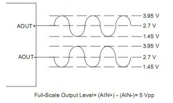
As long as you do not DC ground the center tap on the input side, the 2.7 volts will not cause a current and everything will work.Before I commit to this experiment, I want to be sure that there won't be a problem with the output levels going on. Attached is a diagram from the datasheet of the dac that shows the output levels. There is a 2.7v offset. With that issue, can I still use the transformers directly connected to it because the offset is identical and thus the transformer would effectively block the DC? Or does this mean that I need to correct the 2.7v offset first before I can use a transformer?
Transformers do not have an impedance. On a 1:1 transformer, it reflects the output Z of the Dac, and reflects the load resistor.So from that I know that I need a relatively high impedance input for the transformer, which is why the 10k input was suggested. Now the part I'm concerned about is that in the suggested 10k:10k. The second 10k listed is the load impedance correct? Does that mean that the output impedance is 10k and thus I would need a 100k input impedance on the receiving device, or does it simply mean that it expects a 10k or greater input impedance for that other device?
I like to think of it this way, the output Z of the drivers should be less than 10K and the next stage should be 10K or higher.
Thanks for setting that straight 🙂
I have just noticed an issue with the dac outputs, so I'm going to make another thread and before I try the transformers I'd like to correct the issue. Please check that thread out!
I have just noticed an issue with the dac outputs, so I'm going to make another thread and before I try the transformers I'd like to correct the issue. Please check that thread out!
- Status
- Not open for further replies.
- Home
- Source & Line
- Digital Line Level
- Upgrading the output components in a prosumer dac