Before this upgrading,I drived the platter by a deck motor.I dismantled the simple drive pcb from deck motor,and designed a PLL circuit to replace it.Here are some pics about this DIY:
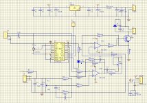
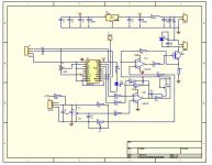
circuit,PLL IC is SANYO LC7991M:
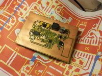
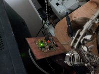
I etched the pcb by myself and soldered it:
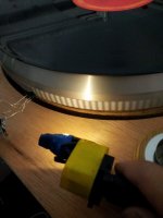
here is the speed photo sensor, black and white strips were atteched on the edge of platter:

The green led will be lighted when the speed is within 33.33rpm+-6%
The final speed is very steady through the control of error DAC in LC7991,test it by 50HZ strobe:
circuit,PLL IC is SANYO LC7991M:

I etched the pcb by myself and soldered it:

here is the speed photo sensor, black and white strips were atteched on the edge of platter:

The green led will be lighted when the speed is within 33.33rpm+-6%

The final speed is very steady through the control of error DAC in LC7991,test it by 50HZ strobe:

Last edited:
Nice to see...
I'm assuming an AC motor? Or Servo control DC motor?
This is a great project. It seems this is relatively simple project but, 6% error is pretty high. Tighter control (+/- .5%) might be a better goal.
I'm assuming an AC motor? Or Servo control DC motor?
This is a great project. It seems this is relatively simple project but, 6% error is pretty high. Tighter control (+/- .5%) might be a better goal.
 Eaglebear please post your attachments using the forum's server, and post an image of the schematic large enough that members can actually see it.
Interesting design. 😀
Hi,nanook!(+-6%) is not the control error,the LC7991 control pins will directly pull high or low when the input signal is out of this range(100HZ+-6%,the crystal is 2.048MHZ,not 11.0592 as schematic),the inner DAC don‘t work.The final control precision is depend on the DAC output,I think the precision should be less than 1%.
Attachment is the datasheet of LC7991.
View attachment 413-12368-0-LC7991M.pdf
Attachment is the datasheet of LC7991.
View attachment 413-12368-0-LC7991M.pdf
Last edited:
- Status
- Not open for further replies.
- Home
- Source & Line
- Analogue Source
- Upgrade belt drive TT by PLL circuit
