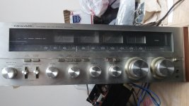
I am repairing a Vintage Realistic STA-2080 amplifier that has a severely overheating LEFT channel.
The Original NEC 2SD745/2SB705 output transistors are BADLY burned, (green PNP colored brown) and still measured good, but I replaced them anyway with MJL3281/1302 Onsemi and at first it seemed stable, but it started thermally running away again. I also replaced BOTH 220 ohm BIAS pots with a 100 ohm+39ohm in series to make bias adjustment less sensitive, and easier to set the quiescent current.
When I measure the 0.5 ohm output resistors, I can set the bias to ~30mV on both channels and it will stay, but after a while it will go to over 200mV and run really hot just on the left channel again. I will push and bend on all the components, and sometimes it will go back to normal, and sometimes not. When it acts up, the bias adjustment will still adjust, but the quiescent current adjusts at a higher rate.
I am suspecting oscillation, or possibly an intermittent component, but the repair shop has no oscilloscope, but the amp still has a paper schematic that came with it, so at least that gives me some peace of mind.
I have resoldered ALL solder joints, but I am getting tempted just to change out ALL the resistors and capacitors with fresh ones, since they are so old, but I would rather just find what is triggering this first, before doing that.
Any ideas or input is welcome!
Last edited:
It most certainly will be a semiconductor. Is the bias transistor coupled thermally to the output heat sink?
I have got myself into trouble with old amplifiers and replacing transistors.
I bought a Maplin 225WRMS amp off ebay with output transistors missing.
I bought in new ones fro ma reputable dealer and the amp worked but I noticed on the output a lot of oscillation.
I had to increase the VAS capacitor a bit to stop the oscillation.
I checked on my semiconductor analyser and the gain was a lot higher on the new transistors than the spec sheet said they should be. This was causing instability.
Thanks for your input guys. I need to clarify that it already had heating issues previously with the original NEC transistors, that is why I changed the transistors. The new transistors actually are slightly easier to set the bias, so I can not say that the new transistors are causing it.
I have to give credit to the original 120W NEC transistors for lasting for years under those conditions, but it is time to retire them.
I used my multimeter to measure the bias VBE POT while on, and now the amp is setting correctly, WTF? I am considering taking Nigel Wright's recommendation and replacing the VAS capacitors with some fresh ones.
I am considering taking Nigel Wright's recommendation and replacing the VAS capacitors with some fresh ones.
I found I had to increase the value slightly to stop oscillation.
PICTURES
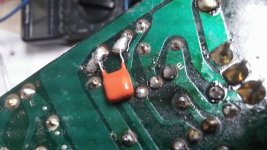
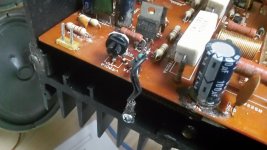
I am posting pics of the AMP, Schematics, and also capacitor across BIAS POT (smooths adjustment)
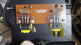
Thermal Diode(s) are a single component screwed on to the heatsink, near bias POT, see picture
I used KAPTON Tape on transistors themselves, because heatsink surface was rougher than the transistors, and used thermal grease too.
BEWARE, pics are huge, I don't have photo editing software, and was in a hurry to post them, sorry.
I am posting pics of the AMP, Schematics, and also capacitor across BIAS POT (smooths adjustment)
Thermal Diode(s) are a single component screwed on to the heatsink, near bias POT, see picture
I used KAPTON Tape on transistors themselves, because heatsink surface was rougher than the transistors, and used thermal grease too.
BEWARE, pics are huge, I don't have photo editing software, and was in a hurry to post them, sorry.
Attachments
-
 STA-2080.JPG444.1 KB · Views: 296
 -
 MJL3281_1302_KAPTON.JPG402.7 KB · Views: 177
 -
 BIAS_pot_bypasscap.JPG476.4 KB · Views: 174
 -
 Bias_pot_mod.JPG517 KB · Views: 221
 -
 Both_Amps.JPG591.1 KB · Views: 174
 -
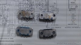 transistorbacks.JPG515 KB · Views: 303
 -
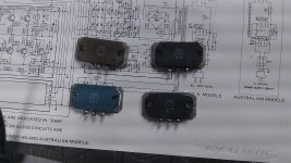 transistorsburned.JPG496.6 KB · Views: 283
 -
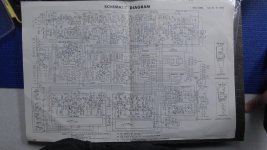 Schematic.JPG587.3 KB · Views: 298
 -
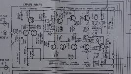 MAIN_AMP.JPG554 KB · Views: 298
Last edited:
This circuits front end looks very much like an old Hitachi lateral mosfet application note.
C509A looks to be very small in size, my circuit shows about 100pf.
Might be worth tacking 100pf across it and seeing if the bias settles down.
C509A looks to be very small in size, my circuit shows about 100pf.
Might be worth tacking 100pf across it and seeing if the bias settles down.
D503A is the culprit. You will find this located on the heatsink. It is open or nearly so.
I've successfully replaced these devices by putting a couple of 1N4002s in series and mounting them on the heatsink. The thermal characteristics are not exactly the same, but it worked so well that it was not worth writing home about.
I've successfully replaced these devices by putting a couple of 1N4002s in series and mounting them on the heatsink. The thermal characteristics are not exactly the same, but it worked so well that it was not worth writing home about.
I was suspecting this part (sort of) but if this part is going open, I wouldn't expect the bias to still be adjustable, being the Bias POT is in series with it......that's where I'm a bit unsure about it.
Would using a darlington transistor substitute the two diodes as a thermal sensor? It would be super easy to mount an isolated TO-220 device.....
However, if not, I could take two silicone diodes in series, mount them in a crimp connector and screw it to the heatsink, similar to the original part.
I will also add 100pf VAS compensation as well.
Last edited:
I will vote for the drivers
find anything close or swap from the other ch see how it goes Point is that measuring them outside will give a hint but under voltage and current transistor might partially fail.
Zero freeze is your companion so freeze any of the drivers to see if bias drops .....
Your suspect wrong about the diode this also might fail under voltage or temperature periodical fail is also a possibility
Kindest regards
Sakis
if you push or bend on something that results in a change; that's a pretty big clue.
can you narrow down which component(including the PCB) that get "pressured" lead to changes?
in my experience, i've seen oscillation, cold solder joints, a hairline crack in a resistor or diode or PCB trace cause similar symptoms, but it sounds like you think you've ruled most of that out?
just to clarify, you did say that when the bias goes high that that adjusting the pot still causes bias changes?
good luck and let us know what the fix is!
mlloyd1
I was suspecting this part (sort of) but if this part is going open, I wouldn't expect the bias to still be adjustable, being the Bias POT is in series with it......that's where I'm a bit unsure about it.
Would using a darlington transistor substitute the two diodes as a thermal sensor? It would be super easy to mount an isolated TO-220 device.....
However, if not, I could take two silicone diodes in series, mount them in a crimp connector and screw it to the heatsink, similar to the original part.
I will also add 100pf VAS compensation as well.
I doubt that the part is completely open.
If you were to have problems with other transistors in the circuit, its unlikely you would be able to set the bias at all- it would just draw too much current as soon as you started to bring up the AC voltage on the variac. Assuming you have one of course...
you are wrong ...again
Often transistors suffer from mechanical failure which obviously might be temperature or current oriented
The die is ark welded on the metal some times after all these years becomes loose Freeze it and ice will make it conduct once more
I have seen it before and depending on the application either the amplifier is overbiased or looses bias totally .
I find my self in a position trying to convince you about that ...I wonder why
One thing I am uncomfortable with.....I just looked up the datasheet on the drivers. 2SA985/2275
They are only rated to 120V, and the amp has over ~55V rails unloaded. This may be unrelated to the issue, but I had to mention it. Again, only issue I have is with LEFT channel, but boy the drivers run hot for both channels.
I am considering replacing with MJF15030/31 Original Motorola transistors that I have.
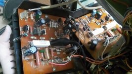
Also noticed on the LEFT channel TR505 has blackened the PCB, but NOT on the right channel. There is also a temp compensation diode that leans against that transistor.
It also has a compensation diode resting against the current source transistor TR503 for the differential LTP.
They are only rated to 120V, and the amp has over ~55V rails unloaded. This may be unrelated to the issue, but I had to mention it. Again, only issue I have is with LEFT channel, but boy the drivers run hot for both channels.
I am considering replacing with MJF15030/31 Original Motorola transistors that I have.
Also noticed on the LEFT channel TR505 has blackened the PCB, but NOT on the right channel. There is also a temp compensation diode that leans against that transistor.
It also has a compensation diode resting against the current source transistor TR503 for the differential LTP.
Last edited:
I've certainly seen temperature sensitive devices. The ones in this amp were not known for that particular defect. Of course over the decades since I worked on these amps the devices could have degraded.you are wrong ...again
Often transistors suffer from mechanical failure which obviously might be temperature or current oriented
The die is ark welded on the metal some times after all these years becomes loose Freeze it and ice will make it conduct once more
I have seen it before and depending on the application either the amplifier is overbiased or looses bias totally .
I find my self in a position trying to convince you about that ...I wonder why
I wasn't aware you were trying to coach me. At any rate, I used to repair these things, did so for years, at the Radio Shack service department located at that time in Midway Center of St. Paul, MN, for the 5-state region of No. and So. Dakota, MN, WI and Iowa. I was head technician and did most of the amps and receivers that came in the door. The description is identical to many that I saw of the same model. Of course, as we both know, troubleshooting at a distance is fraught with difficulties. I'm simply going by the description and my own experience with the product.
I missed the part about pushing on components- in this regard I do agree that power tab devices in general can become intermittent. However, usually they open up if this is the case. That would cause the amp to distort.
D503A is the culprit. You will find this located on the heatsink. It is open or nearly so.
I've successfully replaced these devices by putting a couple of 1N4002s in series and mounting them on the heatsink. The thermal characteristics are not exactly the same, but it worked so well that it was not worth writing home about.
I'm going to take your suggestion and change it out for both channels.
I just discovered with a multimeter that there is some current flowing from the leads of the D503A to the "fork" which is grounded to the heatsink that changes resistance when touched or wiggled.
I hope this is it.
Attachments
Indeed, it would be a decidedly good idea if the bias diode maintained good insulation from the heatsink. Other than that this kind of bias diode can also simply go intermittent, VDxxxx types are notorious for that. D503A/B is an MV-11Y though. Have you checked the bias pot? Sometimes they literally fall apart in old age, or at least are hard to revive.
There are two of those pesky VDxxxx bias diodes still lurking in the circuit actually, D501A/B (VD1221) and D502A/B (VD1121). If in doubt, the appropriate number of 1N4148s soldered in parallel should help narrow things down. Those can also be used to make a makeshift bias diode replacement if need be, just a bit more work due to providing insulation while still maintaing good thermal contact.
There are two of those pesky VDxxxx bias diodes still lurking in the circuit actually, D501A/B (VD1221) and D502A/B (VD1121). If in doubt, the appropriate number of 1N4148s soldered in parallel should help narrow things down. Those can also be used to make a makeshift bias diode replacement if need be, just a bit more work due to providing insulation while still maintaing good thermal contact.
Thank you for that info about those diodes. I'll be working on it again tomorrow, and post some new pics, but I finally got the bias stable after changing that heatsink diode, (FMNG12 TO-220 diode + 1n4001 diode soldered to the leg) AND some transistors (tr507/508/505). So from years of thermal fatigue caused multiple issues. Also upgrading the capacitors reduced some quiet AC "buzz". I'll leave more details tomorrow when I get back to the shop. I will change the other thermal diodes as well now, thank you.
Last edited:
Looking at your pictures of the hot board and the glue holding the capacitors looks a bit suspect, to say the least.
- Status
- Not open for further replies.
- Home
- Amplifiers
- Solid State
- Unstable Bias Realistic STA-2080