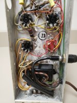
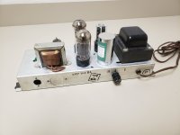
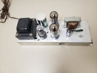
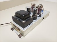
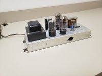
I just recapped a nice little Magnavox 164BA amp. I was surprised to see the frequency response is not flat! not flat at all! looks like a Camels hump! two big peaks top and bottom with a scooped out mid section. I have to imagine this was done on purpose??? I know Sam's schematics are often wrong, but the value of caps i used matched what was in there.
Looking at other Magnavox schematics, I see some differences. I am guessing i should remove C5 and maybe C7??
Looking at other Magnavox schematics, I see some differences. I am guessing i should remove C5 and maybe C7??
Attachments

Removing c7 from the feedback path removed the LF hump. But I still have a major bump at 12.5khz. Removing c5 made no difference. So now I'm looking at c3 the .1uf cap in the cathode of V1. Would that cause a hf bump?
C3, the cathode bypass on the input tube, is so small that it will probably cause some HF gain. Had the same thing recently on another brand of amp from the 50's. May have been to make up for HF deficiency of typical speakers. I had a treble hump of quite a few dB until I removed it. C3 may also be part of the feedback scheme so it may not do what I imagine.
John
John
Ahhh ha! Removing c3 flattened the response! That little bit taught me quite a lot actually!!!!
I added a 4.7uf cap across cs and it made my hf hump bigger and wider and added a bunch of gain, what is what I kinda thought it would do, so I removed c3 and then the response was flat past 20khz!!!
Very interesting
I added a 4.7uf cap across cs and it made my hf hump bigger and wider and added a bunch of gain, what is what I kinda thought it would do, so I removed c3 and then the response was flat past 20khz!!!
Very interesting
If you take out all the frequency dependent elements in the feedback and make it just the ratio of two resistors, the gain is flat to within the limits of the open loop response.
Yeah, this sort of thing was used to “cheat” and give the effect of bass and treble controls turned all the way up. When they started doing cheap 1 watt transistor and IC amps, they quit doing this, and they tended to sound like tin cans if you were used to the “boost”.
Yeah, this sort of thing was used to “cheat” and give the effect of bass and treble controls turned all the way up. When they started doing cheap 1 watt transistor and IC amps, they quit doing this, and they tended to sound like tin cans if you were used to the “boost”.
My father upgraded his Magnavox HiFi to a Silvertone stereo system sometime in the early 60's. The old Maggie became mine. Since I didn't own any records and my parents had given me an electric guitar from the Lafayette Radio and Electronics Catalog for Christmas, but no amp, there was only one thing for the dumm blonde kid to do. Armed with a pair of scissors and some masking tape I had cut the end off of a guitar cable and spliced it to the wires in the tone arm. I had "made" my first guitar amp. Oddly it sounded pretty good and my friend who had a REAL Fender amp and a Hagstrom Guitar liked the sound of my old Maggie better than his Fender. The Maggie had two or three speakers and one of them was big (to a kid who takes apart old radios). It was probably 12 inches.I just recapped a nice little Magnavox 164BA amp. I was surprised to see the frequency response is not flat! not flat at all! looks like a Camels hump! two big peaks top and bottom with a scooped out mid section.
So this is what causes the magic?
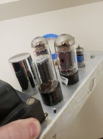
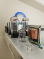
I remember that the amp had 4 tubes, three big ones and one little one. I googled "Magnavox 164BA amp" and it does look like what I vaguely remember. The later versions used 6BQ5/EL84 tubes. My amp definitely used a pair of 6V6GT tubes and a 5Y3 since I used them later for a real DIY guitar amp build. I found some pictures of the consoles that the 164BA went into and one did resemble my father's flip top design.
The tone stack in a typical guitar amp also "scoop's out" some of the midrange by design to reduce harshness.
this little Maggie came out pretty good. Not a lot of power. about 5-8 watts i would guess. I added the fuse holder for safety. I was going to use this for a project but it is just too large physically to fit. so I have put it up for sale.
Attachments
-
 20250317_203109.jpg233.7 KB · Views: 43
 -
 20250317_203101.jpg244.7 KB · Views: 43
 -
 20250317_203049.jpg544.2 KB · Views: 43
 -
 20250317_203046.jpg433.1 KB · Views: 39
 -
 20250317_203041.jpg357.9 KB · Views: 39
 -
 20250317_203032.jpg250.9 KB · Views: 39
 -
 20250317_203022.jpg255.1 KB · Views: 44
 -
 20250317_203018.jpg240.9 KB · Views: 41
 -
 20250317_203013.jpg217.5 KB · Views: 41
Ahhh ha! Removing c3 flattened the response! That little bit taught me quite a lot actually!!!!
I added a 4.7uf cap across cs and it made my hf hump bigger and wider and added a bunch of gain, what is what I kinda thought it would do, so I removed c3 and then the response was flat past 20khz!!!
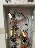
You should continue to adapt this driver circuit toward a common lower impedance design for ''standard'' line levels and input impedances you'll find in other Maggy amps. Consider this design is for the phono cartridge used in the system is obviously a high impedance crystal @5 megs. and the biasing is bootstrapped to the 305v supply. You have removed the DC blocking cap in the FB line so now there is a path for DC into the OPT and that will also change the driver biasing. So the driver bootstapping should go and the plate loads and input impedance changed. The entire input should be cloned to another Maggy amp design you may have the schematic for.

20to20 good points! I never thought about the DC getting back to the output transformer. I figured that 305v bootstrap was to reduce noise by injecting whatever rippled back into the feedback path. the amp is DEAD quiet! i was surprised at how quiet it is. Maybe i can try adding a cap in that line instead of a direct connection??
the 161 amp appears to be very close with a different Input circuit values. maybe this would be better?? I figured whoever bought it might want to convert it into a guitar amp which seems to be the popular thing to do with these old amps. so i figured they may want to change it up anyway.
the 161 amp appears to be very close with a different Input circuit values. maybe this would be better?? I figured whoever bought it might want to convert it into a guitar amp which seems to be the popular thing to do with these old amps. so i figured they may want to change it up anyway.
Attachments

Ya, more like it. And there is an 88-01 stereo you could clone one channel of, keeping in mind the 6EU7 is different pins. There is also a balance control that you would simply use 1/2 of via a single fixed 390R added to the FB line near the driver cathode.
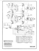
20to20 good points! I never thought about the DC getting back to the output transformer. I figured that 305v bootstrap was to reduce noise by injecting whatever rippled back into the feedback path. the amp is DEAD quiet! i was surprised at how quiet it is. Maybe i can try adding a cap in that line instead of a direct connection??
You just want a bigger cap than was there originally, if you don’t want the bass boost. Using a blocking cap to effectively remove the feedback at infrasonic is one of those tricks you can use to get loop stability at low (single digit Hz frequency), so it does have other legitimate uses.
Agree with that point, too. The point I made about blocking the DC really is a small issue compared to the FB and the FR tailoring that seems to be going on there. Without knowing more about the cabinet system and the speakers and the bass response of the OPT it's a tough to know what the best value would be for that cap. I suspect that the bass boost could be to compensate for small speakers and/or poor OPT bass specs. That PP tranny isn't much bigger than Magnavox used in it's small SE amps.
The DC in the output transformer (and effect on bias) is insignificant since it's through 10K in parallel with 470 Ohms (5% of 2.7 mA). The fixed bias resistor to B+ is a way to increase gain in that stage - cathode resistor is 470 vs. 4.7K for the same operating point. Magnavox made adjustments in the amp to compensate for the cartridge, tone controls, speaker frequency response and relative efficiency. And every one seems to be different.
You beat me to that point about the tone controls. I was just about to say I'd bet the original humps in the FR were designed in so that the bass and treble controls could be set to center with a bit of cut on both and then have a range up and down from there.
Agree with that point, too. The point I made about blocking the DC really is a small issue compared to the FB and the FR tailoring that seems to be going on there. Without knowing more about the cabinet system and the speakers and the bass response of the OPT it's a tough to know what the best value would be for that cap. I suspect that the bass boost could be to compensate for small speakers and/or poor OPT bass specs. That PP tranny isn't much bigger than Magnavox used in it's small SE amps.
The goal back in those days was to make something pleasing to listen to, working around the limitations of the speakers. Flat was never their intention. I did it in my big 200 watt mono blocks to tamp down the last bit of LF ringing. Setting the input coupling cap pole at the same frequency as boost starts (was single digit Hz) restores square wave response.
Somebody in the SS forum was restoring/revamping an old Ge radio that had smiley face EQ built in, and wanted to use a chip amp. We worked through emulating it with op amps, but eventually decided less boost was better since the new speaker had better bass response that the original unbaffled one.
- Home
- Amplifiers
- Tubes / Valves
- Unhumping a Magnavox