Hello everyone,
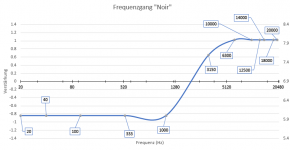
I finshed a DIY AMP and came across an interesting frequency response. My AMP should have an 6dB output but when I went to make the test it started increasing at around 2kHz and hit 8dB at 8kHz.
Can someone explain what the problem could be and what the side effects will be if I keep on using it. I've tested it and it sound good till now.
Thank you for helping me
The graph was made in excel, very amateur but I hope it helps
Attachments
Do you have the schematic? Care to share it?
It's actually the "Noir" Build from Mark Johnson. So you can check the shematic in his thread
...Its like pulling teeth...
Post the schematic or a link to it if you want help.
Noir, a two transistor headphone amp: class-A, single ended, 150mA bias
Not sure what could cause a response like that - I'd run an RMAA loopback test to verify, this this may provide additional clues.
Honestly the best idea I have right now is double-checking that every part is equipped correctly, that the volume pot is connected correctly and that the signal and ground connections on inputs and output (as well as supply voltage and ground) are OK. Taking some voltage readings around the MOSFET and comparing them to simulation results would also be worth a shot, just to make sure the amp is basically doing what it's supposed to.
Honestly the best idea I have right now is double-checking that every part is equipped correctly, that the volume pot is connected correctly and that the signal and ground connections on inputs and output (as well as supply voltage and ground) are OK. Taking some voltage readings around the MOSFET and comparing them to simulation results would also be worth a shot, just to make sure the amp is basically doing what it's supposed to.
There doesn't seem to be any part of that circuit that can have a time-constant around 100µs where you see the response change. Must be a failed component I think, perhaps dry capacitor?
For instance if the 3.3mF output cap had lots of ESR, then the 1µF cap in parallel would boost the output with a cut-off freq depending on a time constant of 1µF x Rload (which for Rload=100 would be 100µs).
Last edited:
- Home
- Amplifiers
- Headphone Systems
- Uneven Frequency Response