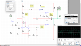
Becuase my knowledge permits me I decided to create something more unsual and experiment a circuit that has main goal to amplify audio and not to work as a computer square wave bufer. This pushed me to keep the amplifying stage as close as possibile to class A operation where I could and optimal class AB where I could not.
Attachments

Looks like in practice it will be all over the place, stability wise.
Make one and see it wobble everywhere. The reasons will be obvious.
Make one and see it wobble everywhere. The reasons will be obvious.
That is not true at all and there is no reaseon for it, I build it this morning and now I am listening at it. I would appreciate if you could name a instability isue, provide an argument to your claim. The design sounds verry good, I listened for 2 hours now, I finished it at 8 PM this morning.
You almost reinvented Rudy Eschauzier's and Johan Huijsing's frequency compensation method from
https://ieeexplore.ieee.org/document/5467933
It boils down to making a common-collector stage with AC grounded emitter.
https://ieeexplore.ieee.org/document/5467933
It boils down to making a common-collector stage with AC grounded emitter.
I hate the Miller compensation so much that necessity made me found another way. The Miller compensation is a kitchen blender for high notes, thank you for appreciating my work.
Sure is unconventional.Becuase my knowledge permits me I decided to create something more unsual and experiment a circuit that has main goal to amplify audio and not to work as a computer square wave bufer. This pushed me to keep the amplifying stage as close as possibile to class A operation where I could and optimal class AB where I could not.
You have very high supply voltage.
And it is a preamp.
But if it works - why not?
You have a very simple system.
And this is good.
I have no doubt it works well.
As you say - no problems.
And this is good.
I have no doubt it works well.
As you say - no problems.
No problems, and it beats all the Harman Kardon amplifiers I had, or Crown Pulse series that try to implement a symetrical signal amplification. I started exploring audio diy with Crown schematics and they are verry complicated, now to be more serious simple is the best way and by this I mean achive the best quality with the most simplest path.
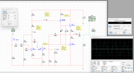
Here is the simulation at 2,83 Volts Rms on output. I had the bias at 15 mV on both 0,33 Ohms resistors with no noticeable problem, and now it is 20 mV for comparing but from what I see not the same thing as BJT that benifit alot.
Attachments
Last edited:
I like your output mosfet stage. It reminds me my experiments with bjt output buffers. Even i used symetrical power supply, i put cap on output simply to eliminate small dc always changing due to temperature drifts.
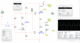
Here is my unconventional preamp. Inspired by @radu2326Can you post 1 watt sine wave sim?
What bias is best?
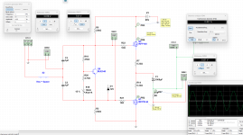
What is good is there is no need for compensation caps.
It is stable.
With my very simple power stage using EXICON Lateral MOSFET.
Output from preamp is only THD 0.004%
Output from power stage is THD 0.046%
The level at output is 8.0Vp-p = 1 Watt into 8 Ohm.
You need to set the simulation conditions to zero in Multisim than we can see if it is an oscillator.
radu2326, thanks, i may build your mosfet output stage. Not immediately, since i started few speaker projects, but maybe in a week or two.Here is the simulation at 2,83 Volts Rms on output. I had the bias at 15 mV on both 0,33 Ohms resistors with no noticeable problem, and now it is 20 mV for comparing but from what I see not the same thing as BJT that benifit alot.
How big is the heatsink?
I suppose q6 mje340 is on the heatsink too, to provide temp sensing.
Can you post the pics?
Just curious.
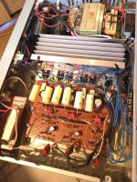
First do not forget about ading a 12 Volt Zenner diode across Q6 MJE-340 and yes Q6 on heatsink and also use a blue multi-turn trimer for fine ajustment. Below is a picture with another driver board but the same output stage as in the schematic, I change the driver board but output stage remains the same all the time. The heatsink is for 3 chanel or 6 Mosfets and I have it ventilated not directcly on fins but a fan blows out silently the hot air if there is.
Attachments
- Home
- Amplifiers
- Solid State
- Unconventional Audio Frequency Amplifier