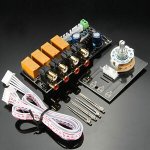
In my designs I do switching of unbalanced inputs using relays controlled by programmable PIC.
I have seen schematics of such circuits where a single relay switches both L&R signal connections while the grounds of each side are wired together and hard-wired to the respective L/R output, while other schematics show a relay is used per input side to switch both the signal and the ground for each input pair so that the grounds of only one input pair are connected at any given time.
My question is this: Is the more complex two-relay-per-input pair with disconnection of the ground as well as the signal either required or desired for best practice? My own sense is that keeping all signal sources at a common ground level is desirable, not problematic, but I'm seeing schematics that cause me to wonder if I'm right.
Either way works, but switching the ground is much less commonly done,
though it can reduce ground loops and hum in some cases.
though it can reduce ground loops and hum in some cases.
If you disconnect the ground as well, that is likely to introduce a thump sound as the component disconnected returns to the same ground level as the selector.
Not a good idea if smps and doubly isolated components are used as they tend to sit somewhere between the live and the neutral of your mains through a Class Y capacitor.
Not a good idea if smps and doubly isolated components are used as they tend to sit somewhere between the live and the neutral of your mains through a Class Y capacitor.
I don't generally switch grounds along with signal, but it can help of you have crosstalk (like when you have it set to input 1 but can hear input 2 faintly at full volume).
Most DPDT signal-only relay switch solutions leave the "off" position of the relay unterminated and therefore the unused inputs (potentially with signal) unterminated. I have wondered about terminating the disconnected input signal with a 5K or 10K resistor on the "off" side of the double throw. Would that help crosstalk or is it simply unnecessary?
Yes, it would help, depending on the layout. Short each unused input with a 1k resistor.
Ideally this would be at or near the RCA input jacks.
Ideally this would be at or near the RCA input jacks.
I lay out my pc board so that the relays are right next to the input jacks so that'll work. I'm surprised by the low value -- 1K -- you recommend. Is that enough to avoid stressing the source?Yes, it would help, depending on the layout. Short each unused input with a 1k resistor.
Ideally this would be at or near the RCA input jacks.
If you're worried, any op amp can drive 2k, so use that instead.
A tube source won't be damaged by shorting its output, so just make sure
that the tube source has a resistor to ground after its coupling capacitor,
to avoid pops when switching its inputs.
Some use an input pcb with all RCA sockets, relays, connectors for wiring to the audio circuit, etc.
A tube source won't be damaged by shorting its output, so just make sure
that the tube source has a resistor to ground after its coupling capacitor,
to avoid pops when switching its inputs.
Some use an input pcb with all RCA sockets, relays, connectors for wiring to the audio circuit, etc.
Attachments

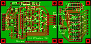
My current design is custom-sized to match my PIC-controlled LDR volume control, and it's pretty tight with four inputs. In order to add 2K resistors and keep the size constant I may have to reduce the input count to three, but the relays will remain close to the input jacks and I really don't need even three inputs, two would be enough.If you're worried, any op amp can drive 2k, so use that instead.
A tube source won't be damaged by shorting its output, so just make sure
that the tube source has a resistor to ground after its coupling capacitor,
to avoid pops when switching its inputs.
Some use an input pcb with all RCA sockets, relays, connectors for wiring to the audio circuit, etc.
Attachments
I've never switched ground in all the relay based input selectors I've made and never had a problem with hum or noise. I would worry about introducing a thump when switching the ground.
The input cable connector shields should be terminated to the chassis.
Otherwise it's just an unbalanced version of the "Pin 1 Problem".
Otherwise it's just an unbalanced version of the "Pin 1 Problem".
I have always kept the signal ground independent of power ground and chassis ground with power and chassis grounds connected to each other, so your advice is a new wrinkle for me. Are you saying direct-to-chassis, or some kind of resistor/capacitor between input ground and chassis? Are you saying that output ground should also be grounded to chassis (and to input ground)?The input cable connector shields should be terminated to the chassis.
Otherwise it's just an unbalanced version of the "Pin 1 Problem".
I'm saying:
a] an RCA chassis jack shell should be connected to the chassis at the jack.
b] the AC supply ground should be connected to the chassis near the cord inlet.
c] the audio circuit common should be connected to the chassis at a single point near the input jacks.
(this may be thru a low Ohm resistor or network)
d] the DC supply common should be connected to the chassis at the same single point as the audio circuit common.
- Home
- Source & Line
- Analog Line Level
- Unbalanced Input Switching -- signal only, or signal and ground?