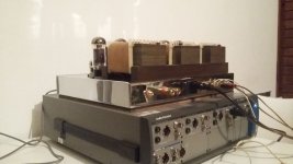
Good evening everyone, about 10 years ago I started with the design of a stereo amplifier, thought of as a double monoblock in a single chassis.
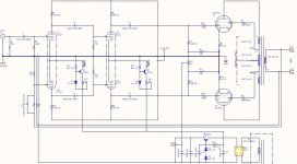
The design was completely symmetrical, with constant current sources in each of the signal stages (two differential pair stages), with global VFB only. For this I considered a good open-loop performance with the idea of having only 12dB of feedback. the tubes chosen were 12AX7A for the input stage, with a constant current source of 3mA in cathodes, this differential pair is followed by another that, in addition to amplifying voltage, has a greater capacity to deliver current to the grids of the output tetrodes, so for the second stage I used 6CG7 with a 7mA constant current source, the output is ultralinear connection with 6L6GC with fixed bias.
Total open loop gain was 46dB, (33.5dB closed loop).
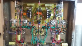
The entire amplifier was designed by me, including the mains and output transformers. In both I used UI cores and two coils.
Some time ago I published the development in a forum in Spanish, since it is my mother tongue, both the calculation and testing process, and its DIY construction, although the measurements were very good at the time, they were made in a rudimentary way. Recently i was able to make more serious measurements with the help of a colleague, which I upload now, shortly I will translate the development and publish it in this thread. My intention is to start manufacturing it on a small scale with a view to marketing it in my country, although it's still a future project
I appreciate your comments and appreciations.
View attachment Roll Test ProudSound A50 V1.0.pdf
PD: sorry for my very poor english, i'm using google translate for now.
The design was completely symmetrical, with constant current sources in each of the signal stages (two differential pair stages), with global VFB only. For this I considered a good open-loop performance with the idea of having only 12dB of feedback. the tubes chosen were 12AX7A for the input stage, with a constant current source of 3mA in cathodes, this differential pair is followed by another that, in addition to amplifying voltage, has a greater capacity to deliver current to the grids of the output tetrodes, so for the second stage I used 6CG7 with a 7mA constant current source, the output is ultralinear connection with 6L6GC with fixed bias.
Total open loop gain was 46dB, (33.5dB closed loop).
The entire amplifier was designed by me, including the mains and output transformers. In both I used UI cores and two coils.
Some time ago I published the development in a forum in Spanish, since it is my mother tongue, both the calculation and testing process, and its DIY construction, although the measurements were very good at the time, they were made in a rudimentary way. Recently i was able to make more serious measurements with the help of a colleague, which I upload now, shortly I will translate the development and publish it in this thread. My intention is to start manufacturing it on a small scale with a view to marketing it in my country, although it's still a future project
I appreciate your comments and appreciations.
View attachment Roll Test ProudSound A50 V1.0.pdf
PD: sorry for my very poor english, i'm using google translate for now.
Attachments
Last edited:
hi pwgtang, in early days I used 12AU7 instead of 6CG7, but with worse results than now, the driver stage did not have enough speed to vary the maximum voltage excursion to the output stage grids at the top frequency limit. Likewise, the 6CG7 is a better valve, has greater plate dissipation, less internal resistance, more linear and cheaper than the 12AU7.
PS: the constant current source of the 12AX7A is 3mA, not 7, for each triode circulate 1.5mA steady state
PS: the constant current source of the 12AX7A is 3mA, not 7, for each triode circulate 1.5mA steady state
Really nice results. Congrats.
Good choice for the 6CG7. This is a fantastic tube. Never had a bad sounding one.
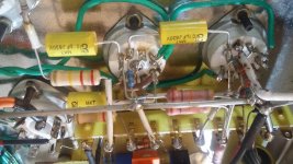
For the CCS you use MJE340G type? It's difficult to read.
For the OT, you used 2 coils for primary and secondary on each coil?
Looks like you used bifilar winding on the primary for perfect symmetry, isn't it. Very nice.
Thanks for sharing.
Brice.
Good choice for the 6CG7. This is a fantastic tube. Never had a bad sounding one.
For the CCS you use MJE340G type? It's difficult to read.
For the OT, you used 2 coils for primary and secondary on each coil?
Looks like you used bifilar winding on the primary for perfect symmetry, isn't it. Very nice.
Thanks for sharing.
Brice.
A few things I noticed:
-You used 100k grid stoppers on the 6L6's, this is at least an order of magnitude higher than what is usually used. Is there a particular reason for this?
-The bias network should probably be reconfigured to improve reliability. Currently if either of the pot wipers lifts from its track you will lose bias voltage
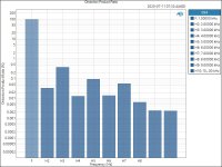
-There is a 4 dB peak in low frequency response, might lead to motorboating in some circumstances?
-You used 100k grid stoppers on the 6L6's, this is at least an order of magnitude higher than what is usually used. Is there a particular reason for this?
-The bias network should probably be reconfigured to improve reliability. Currently if either of the pot wipers lifts from its track you will lose bias voltage
-There is a 4 dB peak in low frequency response, might lead to motorboating in some circumstances?
Changing the 6L6 grid stoppers from 100k to 10k might be a good idea.
Ultra Linear Mode has significantly more Miller Effect capacitance than Beam Power Mode.
But now the pole frequency of the 6L6 g1 will be moved up in frequency.
You may have to change the feedback network capacitor that is across the feedback resistor.
Ultra Linear Mode has significantly more Miller Effect capacitance than Beam Power Mode.
But now the pole frequency of the 6L6 g1 will be moved up in frequency.
You may have to change the feedback network capacitor that is across the feedback resistor.
Blaxshep,
If this is a Hi Fi amp, the designer may want to limit grid current if the signal level is adjusted too high (into clipping).
And that will give a very nice much shorter recovery time for the voltage across the coupling cap.
Blocking distortion in a Hi Fi amp is a no no.
Blocking distortion in a Guitar amp may be all the rave, and cause the girls to swoon.
I think I know who you are 2n3055, I have one transformer you built for me..
Congrats on the great design, hope we can see a prototype in the near future!
Congrats on the great design, hope we can see a prototype in the near future!
hi brice, yes, the NPN on constant current sources ar MJE340, in the bias voltage regulator i put a MJE350Really nice results. Congrats.
the OPT is complex to describe, because it have eighteen windings divided in two coils.. assorted to compensate resistance and coupling inbalances, it have near perfect resistance balance in each half primary winding. 100Hy plate to plate primary inductance, and little 21mHy of leakage primary inductance (secondary windings shorted).
great question, this stopper resistors are intended to limit the charging current of coupling caps on clipping time, in particular with low resistance stages like 6CG7+27K plate resistors.A few things I noticed:
-You used 100k grid stoppers on the 6L6's, this is at least an order of magnitude higher than what is usually used. Is there a particular reason for this?
In the design process I tried different alternatives, one of them was to decrease the anode current of the driver and use higher value plate resistors, to limit the charging current of the coupling capacitors, but although I got the result Expected from the point of view of limiting crossover distortion during clipping, it lost too much bandwidth by having anode-cathode capacity and miller capacity at the driver stage controlled by a much lower anode current.
I also took into account the maximum resistance for 6L6 grid1, for fixed polarization, to which they recommend values of grid resistors of lesser value, although in the 10 years that the equipment has with its original valves, I had no problems until now.
This is an interesting suggestion, although it is true, I pray, until now I had no problems with Bourns 3296W type presets-The bias network should probably be reconfigured to improve reliability. Currently if either of the pot wipers lifts from its track you will lose bias voltage
i´m still thinking what can be happening on this... no, it´s not a motorboating phenomena..-There is a 4 dB peak in low frequency response, might lead to motorboating in some circumstances?
We made the measurement with AudioPrecision APx52x, which has a maximum sweep speed of five seconds between Fmin and Fmax (CC up to 80Khz). we noticed that the faster we did the sweep, the higher the response peak close to 10Hz. A while ago I did a sweep with a function generator direct on the transformer and noticed that if the frequency change is very abrupt from a subsonic value (practically DC), when the frequency reached a value such that the transformer would come out of saturation, a small peak voltage in a half cycle appears ... I'm seriously thinking if the problem lies there ... and seeing to narrow the band through low frequency even more.
ehm.. no, i don't think so, i'm not in the audio transformer fabrication bussines until now.. Anyway, I have a slight suspicion of who you can be ..I think I know who you are 2n3055, I have one transformer you built for me..
- Home
- Amplifiers
- Tubes / Valves
- ultralinear pushpull amp design