I'm about to build an integrated amp based on two ucd180hg modules. I've read Hypex's app notes and I don't really feel at ease with their suggestion to go class II if building it unbalanced.
Furthermore, I plan on using a motorized pot kit for volume control... but the pot in that kit is 100k, so I need a buffer in between the pot and the UCD's input.
So I was considering the following:
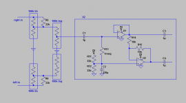
- Building the preamp section (see schematic below) and using a ground loop breaker in between the audio ground of the preamp and the enclosure. All the input section would be isolated from the chassis. Since I've got 2x12vac transformer for the auxilliary stuff, I can use a winding to power the preamp.
- Connecting the chassis to earth and to the audio gnd of the amplifiers (by earthing the midpoint of the power supply).
Any problems with that way of proceeding ? Is a shielded connection between the preamp and the amps really needed inside a box ? If yes, where do I connect the shield at the preamp side ? Right where the ground loop breaker is tied to the chassis ?
Furthermore, I plan on using a motorized pot kit for volume control... but the pot in that kit is 100k, so I need a buffer in between the pot and the UCD's input.
So I was considering the following:
- Building the preamp section (see schematic below) and using a ground loop breaker in between the audio ground of the preamp and the enclosure. All the input section would be isolated from the chassis. Since I've got 2x12vac transformer for the auxilliary stuff, I can use a winding to power the preamp.
- Connecting the chassis to earth and to the audio gnd of the amplifiers (by earthing the midpoint of the power supply).
Any problems with that way of proceeding ? Is a shielded connection between the preamp and the amps really needed inside a box ? If yes, where do I connect the shield at the preamp side ? Right where the ground loop breaker is tied to the chassis ?
Attachments
why is that? seems good advice on their part. (it's depending on the PS design ratings used) but with balanced you should add a third wire without fear of mains induced hum. consumer stuff E.g. your sources might be best sticking with class II.I'm about to build an integrated amp based on two ucd180hg modules. I've read Hypex's app notes and I don't really feel at ease with their suggestion to go class II if building it unbalanced.
pot loading for log law pots isn't a big deal with in reason, but channel matching is more of a concern. I wouldn't start adding stuff > ground loop breaker, and buffers until it needs them. ground loop breaker is a big band-aid aid after introducing a third wire , stuff cracks me up.
perhaps yer overthinking your build before a problem arises.
Last edited:
why is that? seems good advice on their part. (it's depending on the PS design ratings used) but with balanced you should add a third wire without mains fear of induced hum. consumer stuff E.g. your sources might be best sticking with class II.
It's simply because I feel safer building stuff with a properly earthed enclosure. The PS will be using a conventionnal transformer+diode bridge+caps design. And it has to work with consumer gear. 🙁
ground the enclosure then but leave the audio grounds floating. use twisted wire pairs for inputs and outputs. shielding isn't required on amp levels.
assuming the transformer rated for commercial class II and you use best commercial mains wiring practice.
assuming the transformer rated for commercial class II and you use best commercial mains wiring practice.
Last edited:
Which is something that Hypex strongly advices against: http://www.hypex.nl/docs/appnotes/earth_appnote.pdf
adding a third wire becomes more complicated with unbalanced not the other way around
do you have RFI with any commercial gear at your place?
I don't get it, you 1st didn't agree with your amp vendors suggestion now you use them to argue against me?
ground everything in sight dude and then cry about ground loops and hum.
do you have RFI with any commercial gear at your place?
I don't get it, you 1st didn't agree with your amp vendors suggestion now you use them to argue against me?
ground everything in sight dude and then cry about ground loops and hum.
Last edited:
That much I had gathered 😉adding a third wire becomes more complicated with unbalanced not the other way around
Who hasn't these days ? In particular, the amp will sit next to a wireless router, a dlna server, etc. I'd rather avoid taking chances.do you have RFI with any commercial gear at your place?
I don't agree with self made class II devices. It doesn't mean I can't see the wisdom in not letting the amplifier float. Hence the original question.I don't get it, you 1st didn't agree with your amp vendors suggestion now you use them to argue against me?
just search the chip amp forums for "loop ground breaker". and all your questions are answered BTW your grounded chassis is the shield and all amps need RFI filters at their inputs, if they left it off then they failed.
hum, no. The chip amp forums has plenty of general info on ground loop breakers, which I don't need. I've built enough dead silent amps to know how to use those. Most chipamps don't have a differential input as the ucd180 either.
The questions in the original post are about a particular implementation. Let's try with other words: if I float the input buffer (which is simply a basic unbalanced to balanced converter) with a ground loop breaker, is there still a path for a ground loop if I earth the amp section ?
The questions in the original post are about a particular implementation. Let's try with other words: if I float the input buffer (which is simply a basic unbalanced to balanced converter) with a ground loop breaker, is there still a path for a ground loop if I earth the amp section ?
i don't see any purpose for the buffer in the receiving section, infact C2 provides a dead AC short to the non floating ground. If it was me i would build the buffer at the sending end and use pro balanced connectors. otherwise consider BALUN transformers to break system grounds up AFAIK that's what the chip amp vendors ( lawyers?) suggest for those who insist on Class I gear and experience ground loop noises.
Last edited:
Building the buffer at the sending end isn't an option since the sending end is made of half a dozen pieces of consumer gear.
Could you clarify what you mean by "non floating ground" ? All the grounds in the schematic, including c2's, are tied together and are connected to the "floating" end of the ground loop breaker.
Could you clarify what you mean by "non floating ground" ? All the grounds in the schematic, including c2's, are tied together and are connected to the "floating" end of the ground loop breaker.
wow 6 sources? IDK seems like building a switched input , volume controller, and line out buffer box might be worthy idea then? house the amps in a speaker box, powered monitor speakers are all the rage. move on up to XLR cables.Building the buffer at the sending end isn't an option since the sending end is made of half a dozen pieces of consumer gear.
Could you clarify what you mean by "non floating ground" ? All the grounds in the schematic, including c2's, are tied together and are connected to the "floating" end of the ground loop breaker.
again not a fan of the loop breaker thingy*, are you going to convince any safety guys that your transformer secondary is really floating from PE too.
*I think it was born from a one off deal by an unlucky commercial guy getting his nuts caught in the UL vise. don't see it in any gear today LOL
Last edited:
You truly want me to modify half the system, don't you ? The speakers are commercial and cannot be modified either. So the switched input, the volume control and everything electronic have to go into the amplifier box.
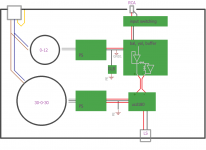
draw your proposed grounding and DC power scheme on a block diagram level
label PE gnd, signal gnd, power amp or digital gnd, etc
BTW the class D digital noise appears as CM on its gnd and should be well isolated from signal gnd at the differential interface, signal transformers work very well and best of all they don't need power supplies that's one reason why I suggested a split or outside the box approach for yer active buffer circuits.
Fire up a class D PA look at gnd with an O-scope its very eye opening to say the least. basically you want to keep the D amp floating at all inputs / outputs by use of differential lines and for DC power, apply CM chokes very liberally. Look up how to make a common mode toroid choke with pairs of wires, very useful for floating or isolating hash from power circuits.
Last edited:
No.ground the enclosure then but leave the audio grounds floating. ................
assuming the transformer rated for commercial class II and you use best commercial mains wiring practice.
All exposed conductive parts should be connected to the protected chassis.
This rule REQUIRES that the Chassis is protected and that any conductive (i.e. metal, or carbon fibre, or similar) are effectively connected such that the connection can pass Fault Current to Protective Earth in the event of a catastrophic Mains Failure.
It's these extra connections that blow the fuse (after a very short delay) and make the equipment safe to touch after the incident.
If you have some existing ClassII equipment, i.e. double insulated equipment, do not alter them.
You are not allowed to alter the circuits/connections inside any commercially constructed and tested and guaranteed ClassII product.
If someone was injured, or worse killed, after you altered a ClassII product you would be liable to prosecution and your household insurance company would refuse to cover you. The consequences would be dire !
Connecting a ClassII source to a ClassI amplifier would use the interconnect as the escape route for a Mains Fault in the ClassI product.
This in turn requires the interconnect to ultimately connect with the Protected Chassis of the ClassII amplifier.
Building a normal ClassI amplifier (or other audio equipment that has either output or input connectors) will provide this escape route if one applies the two rules.
Connect PE to Chassis.
Connect all exposed conductive parts to Protected Chassis.
There is a problem in ClassI equipment that does not seem to be addressed in current legislation (judging by what I see in equipment). If a child puts an unterminated interconnect into it's mouth, does that create the escape route for an un-diagnosed Mains Fault in the ClassI product?
I have asked this question twice before, no one answered.
Last edited:
yes the grounded metal chassis covers any exposed mains, AND best wiring practices makes them less exposed even if the cover is removed. I reckon the OP knows enough to use an IEC fused connector. your other messages is convoluted at best, no one is modifying any type of class gear.nanny outburst.
Last edited:
- Status
- Not open for further replies.
- Home
- Amplifiers
- Class D
- UCD180 grounding, earthing, and the like...