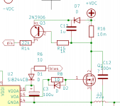
Hello forum people,i've been thinking about implementing it like this,would be much easier than ir2110,faster gate drive ,no level shifters etc.Comparator would need to be able to run from +-2.5 volts but i'm sure it's no biggie.Some compontents are omited or have no values yet,don't worry

Looks good. Suggest you search for a CMOS comparator. In an old project I used TLC339 (CMOS LM339) and equivalents. They need load resistor but there are other with pushpull output: TLC372, my project run 420KHz and was very fast. I also suggest replace 100uF boot caps by a 1 or 2.2uF, too high those will cause start up problems including burn output FETS because of insufficient gate drive voltage.
you are right about bootstrap capacitors,but too low could also cause a desaturation problem,i'm not looking to run too fast because I want to drive some subs with quite high power.Back in the day I used to have the amplifiers in the pc cabinet just like you,and now i'm planing to do the same again,just a couple of orders of magnitude more power.However your seems to be a clocked design,and that could be an option since i'm looking to drive just subs for the moment,pre filter could be simpler to implement in my case but i'm afraid of blowing my output capacitor from undamped resonance,though i've never had that problem before
The problem with self oscillation circuits is that they are really difficult to design IMO and to search a fault in case of problems.
Clocked are more simple because you can design each part independently of the rest and trace a faulted one is easier.
Regarding boot caps, I never checked, but may be combined a low value for it (1 to 2uF) and a larger one (100uF) with a small series resistance, say, 22 or 47ohm. So short term current is managed by the former and long term by the latter.
Last edited:
Yeah,that sounds like a good ideea but i've never seen it in schematics,to be fair I have an d4k5 running and it has an 100u elco bypassed with 100n on the bootstrap,it struggles a bit to start up but can hold the positive mosfet on for like 30 seconds,so that's overkill,the period for 20hz is 50ms,and that;s assuming you are running into very hard clipping I think it's a non issue to be honest.Right now i'm trying to wrap my head around current sensing and short circuit protection,some designs like iraudamp1 and d4k5 only sense the current going through either the upper or the lower fet,and I have no idea if that is good enough for the real world,but it would make things a lot more simple.Do you know anything regarding this ?
I suggest a current transformer. As you have a high frequency switching, it's easy to build on a small ferrite toroid a current transformer, and from its secondary rectifier peak to peak, you take the action whished: shutdown the entire amp, indicate via a led for warning, etc.
Also using several of them you can test each arm current (top and bottom MOSFET) and load current indepently and, again, take an action.
I repaired thousands of AC/AC converters for 3 phase motors from 500W to several KW and once repaired, I mentally studied the circuit.
There are several current tranformers manufactured ready to use, some of them are internally closed loop. Some give you a DC voltage proportional to current sensed, and others a current. But in my experience, all them relies on a hall effect and a true current traffo, and a opamp. But invariably most of them suffer from DC bias at their output as a consequence of overload (a powerfull shortcircuit in the sensed current that manetizes the iron path) or resistor aging or SMD trimpots becaming noisy.
Attachments

No. Most ferrites are good for high frequencies but not in too low. But you can put it previous to filter where RF is present.
yes but a low frequency component will always exist,it's not like in an smps where the top and lower fet are always on for the same period of time
Are you sure you even want to switch the MOSFETs faster? you could have problems with dv/dt at the center of the halfbridge, overshoot etc. Low side sense is standard for OCP you need it to be fast to save the devices
There are SMPS unipolar like Forward and Flyback converters.
I'm now unsure if low frequency may be an issue. Perhaps anothermore skilled than me can help us.
I'm now unsure if low frequency may be an issue. Perhaps anothermore skilled than me can help us.
Fast enough to get low ish switching losses,the switching frequency i see no reason to be higher than 250khz.The issue with one sided current sensing is that if you get a short when the other fet is conducting it will not be protected,whether that is a problem or not,i'm not sure,that's why i'm asking
I think flyback and forward use resistors for current sensing because it's easy to do when you only have a low side fet,or are you hinting at a gapped current transformer?thing would be pretty big i guess
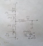
Theorethically a short could not last for more than 25 ms (half of a 20hz period),and a mosfet could probably survive that if it has a long enough time to rest afterwards for the heat to migrate out.Pictured is the over current detector I had pictured,altough I should use a monostable circuit to get a 1-3s cooldown time rather than the capacitor
Attachments
should be fine the short is connected through the inductor of the output filter so is limited in di/dt. You can limit the maximum duty cycle to reduce the bootstrap capacitor size and also ensure that you have a chance to sense the short current. Make sure your OCP retry is not too rapid. High side sense will be tricky!Fast enough to get low ish switching losses,the switching frequency i see no reason to be higher than 250khz.The issue with one sided current sensing is that if you get a short when the other fet is conducting it will not be protected,whether that is a problem or not,i'm not sure,that's why i'm asking
put the current transformer in series with the inductor or simply add a sense winding to the output inductor
yes but that would cut into my voltage swing,and i plan on sticking with 200v mosfets,high side seemed the easiest to me since it can pull up on something easilyshould be fine the short is connected through the inductor of the output filter so is limited in di/dt. You can limit the maximum duty cycle to reduce the bootstrap capacitor size and also ensure that you have a chance to sense the short current. Make sure your OCP retry is not too rapid. High side sense will be tricky!
- Home
- Amplifiers
- Class D
- Ucd style with si8244 gate driver