Hello,
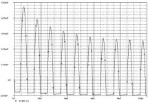
I am building a simple two stage amp that consists of a CE stage followed by a CC state. When the load is sufficiently high i.e. 1k, the output it a clean sine wave. However, for a 10 ohm load or a speaker load of 8 ohms, the output gets clipped off at the bottom. I have attached a schematic and plot of the simulation. The simulation matches what is actually happening on my breadboard testing.
Notice in the simulation plot, the bottom of the sine wave gets clippped for a 10 ohm load. However, at the input to the CC stage, the wave looks clean. So the CC stage is distorting the output. Anyone know why this is happening and any suggestion of how to fix it?
Thanks,
Mark
Attachments

It is happening because a common collector stage that is called an emitter follower may be viewed as a diode linearized by feedback. For the upper half-period your transistor delivers current to the load; but for the lower half-period of the sine the resistor in it's emitter delivers the current to the load.
Now, what do you need to change to get higher negative current delivered to the load?
Now, what do you need to change to get higher negative current delivered to the load?
It is happening because a common collector stage that is called an emitter follower may be viewed as a diode linearized by feedback. For the upper half-period your transistor delivers current to the load; but for the lower half-period of the sine the resistor in it's emitter delivers the current to the load.
Now, what do you need to change to get higher negative current delivered to the load?
The output of your amp is grossly mismatched to the load.
You need to lower the output impedance of the final stage.
The output of your amp is grossly mismatched to the load.
You need to lower the output impedance of the final stage.
It is the answer with common words.
I've asked, what needs to be done to get it right?
Ok so when the current through the 10 ohm resistor into the emitter equals the dc bias current, the transistor cuts off right, thereby clipping the negative half cycle?
Is this why people go with a push-pull output stage instead of the single-ended design?
Is this why people go with a push-pull output stage instead of the single-ended design?
You need to put in a transistor to drive the negative half cycle.
You would then need to bias the output stage in class b if your not fussy about the quality or class AB if you want a decent sound.
Look up class ab output style. There are literally hundreds of circuits out there on this forum and elsewhere.
You would then need to bias the output stage in class b if your not fussy about the quality or class AB if you want a decent sound.
Look up class ab output style. There are literally hundreds of circuits out there on this forum and elsewhere.
The output of your amp is grossly mismatched to the load.
You need to lower the output impedance of the final stage.
Clearly said Anatoliy.
How about this: this output stage (emitter follower) is a class A stage. Therefore, it can only deliver non-clipped signal at 2*quiescent current, which I think is about 3.9V/390ohms *2 is about 20mA into 10 ohms which in turn is about .2V peak-peak. So any signal above that causes clipping because even if the transistor completely closes up, the emitter resistor cannot sink more current.
Solution: increase the standing current by decreasing Re. But watch the heat in that emitter follower!
Or go to a push-pull stage in class AB/B as mentioned. Then you have two transistors that can take turns in sourcing and sinking to arbitrary amounts of current (within reason).
jd
Solution: increase the standing current by decreasing Re. But watch the heat in that emitter follower!
Right Janneman;
It is one half of the answer;
another half is, a standing voltage on emitter must be 2/3 of the B+, instead of a half of it.
Thanks for all the replies.
Wavebourn, why is it neccessary to have 2/3 of B+ on the emitter? It seems like you could have just whatever as long as you are drawing enough current through the emitter resistor to allow for the full voltage swing. Can you further explain this? Thanks
Mark
Wavebourn, why is it neccessary to have 2/3 of B+ on the emitter? It seems like you could have just whatever as long as you are drawing enough current through the emitter resistor to allow for the full voltage swing. Can you further explain this? Thanks
Mark
Thanks for all the replies.
Wavebourn, why is it neccessary to have 2/3 of B+ on the emitter? It seems like you could have just whatever as long as you are drawing enough current through the emitter resistor to allow for the full voltage swing. Can you further explain this? Thanks
Mark;
what do you mean enough? Do you have an unlimited supply?
Suppose, you still want your amp to be efficient, i.e. to deliver max power on the load per dissipated watt.
Member
Joined 2009
Paid Member
You need to use Ohm's law to work this out.
The reason it's not B/2 is because R7 is not a constant current, but depends on the output voltage.
The reason it's not B/2 is because R7 is not a constant current, but depends on the output voltage.
Ok thanks.
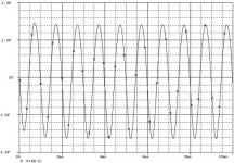
I have noticed another problem as well. When the Rload is 1k, the output for the positive half cycle is much higher than it is for the 10 ohm load. Why is this? For example, for the 1k load, I get a positive peak of just over 1v but for the 10 ohm load, I get only like 200mV peak. It drops to 1/5th of the voltage of the larger load.
I have noticed another problem as well. When the Rload is 1k, the output for the positive half cycle is much higher than it is for the 10 ohm load. Why is this? For example, for the 1k load, I get a positive peak of just over 1v but for the 10 ohm load, I get only like 200mV peak. It drops to 1/5th of the voltage of the larger load.
Ok thanks.
I have noticed another problem as well. When the Rload is 1k, the output for the positive half cycle is much higher than it is for the 10 ohm load. Why is this? For example, for the 1k load, I get a positive peak of just over 1v but for the 10 ohm load, I get only like 200mV peak. It drops to 1/5th of the voltage of the larger load.
The 47uF is not big enough to drive into 10 ohms.
It needs to be much bigger.
I think it also has to do with the gain on the CC stage dropping also right? For the 10ohm load the gain A=10/(10+rm+R looking through emitter). rm and the resistance looking through the emitter are small compared to 1k so the gain is about 1(i.e. 1000/(1000 + small) is 1). But for 10 ohms, they are substancial right?
I think it also has to do with the gain on the CC stage dropping also right?
Right.
Member
Joined 2009
Paid Member
I don't think the capacitor is a big part of the picture unless you are at low frequencies where the impedance of the capacitor become a decent fraction of the load resistance.
The issue is that the 10 Ohm load represents a burden on the output. For a particular signal (voltage) level the current draw from the amplifier will be much higher for a low resistance load. This current has to flow through the internal resistances of the amplifier output stage. If this internal resistance is high, there will be a voltage drop across it and your signal will be diminished.
Have a look at this: http://en.wikipedia.org/wiki/Maximum_power_theorem
The design you have is a good learning tool, but it's not optimal as an amplifier. A resistive load for a single ended Class A amplifier is the worse possible option in terms of power efficiency. You would be better to 'invest' in an additional transistor configured as a current source in place of the load resistor. There is much you can read on this topic.
Your original design is basically useless.
You need to start again with yoru design specification and work from there.
Your taking the wrong circuit and tyring to make it fit and that is the wrong approach to design.
How much power do you need into the 10 ohm load ?
Whats the maximum voltage swing required ?
Whats the input impedance required of your amplifier ?
What power supply do you require.
Thats just for starters.
Member
Joined 2009
Paid Member
Well not completely useless. You have already learned something new and you have taken the effort to understand how things work. The fact that you are actually building something (you mentioned in post no. 1) puts you ahead of some on this Forum🙂
I would suggest some background reading would significantly improve the pace of progress.
Here a couple of suggestions:
http://sound.westhost.com/
http://www.tcaas.btinternet.co.uk/index.htm
I would suggest some background reading would significantly improve the pace of progress.
Here a couple of suggestions:
http://sound.westhost.com/
http://www.tcaas.btinternet.co.uk/index.htm
- Status
- Not open for further replies.
- Home
- Amplifiers
- Solid State
- Two Stage Amplifier Question