I have been away from the hobby for quite a while. Picking it back up, and have been reading about PS here. I have seen a number of posts to NOT connect more than one bridge to a secondry center tapped transformer. Posts mention it being a bad idea, noise wise, to very ominous, BOOM result. The latter certainly got my attention, but I think it is in relation to trying to run two bridges to seperate the rail voltages.
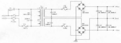
Context: I have an Adcom 545II amp, which has a 500VA transformer. From the schematics (see below), the transformer looked to be just a center tapped one. But, the transformer has 5 wires on the secondary side. The resistance is too low for me to confirm if there are two seperate windings, tied together in a common center tap, or a single winding with extra wires. If someone knows which, I would appreciate it.
Back when, I purchased an Avel 625VA 40-0-40 transformer to mod the amp. I was planning to connect secondaries in series to make a center tap, and feed two bridges and seperate cap banks. One bridge/bank per channel. I didn't think that this would be a BOOM issue, but please, please, correct me here. Now, I could seperate the windings and use two bridges to seperatly rectify the rail voltages, and have a common supply that feeds both channels, but thought the former was better, ie each channel would have its own bank. Certainly will go that way if the CT is a BOOM problem.
I would appreciate your knowledge and comments.
Attachments
Last edited:
Only one diode bridge and center tapped is fine from the very old tube era. As the secondary of the traffo is grounded, is less capable of catching noise from line.
If connected the power rails to the amplifier as shown, both channels will draw current from the transformer (through the Greatz rectifiers) 'in tandem', and this can/will deplete the energy stored in the electrolytes considerable on a more rapid rate then the recharging will happen: most energy is needed around the 250Hz (4msec) region, whereas the charging is at the rate of 50/60Hz (20/17msec). For a separated dual supply in a main amp it is more wise to have one bridge cross-connected to the transformer, avoiding deep depletion. Noise will be somewhat less, but will occur whatsoever. There is more to say about this issue when using multi (separated) windings from one transformer, or using more (single winding) transformers all cross-connected in various ways to minimize noise, charging peak currents and cap-depletion, in advance.
Hi. I will add my few cents. Lets assume we have one center tapped secondary and one common for both stereo channels diode bridge, and lets say 20000 uF for each positive and negative voltages ,feeding both channels. And compare it to situation ,where we have two diode bridges and two capacitor banks ,of half capacity , each channel 10000uF . Pure theoretically, if both channels will play the same, then it should make no difference. Even better with two bridges , diode drop will be lower because current is half and voltage should be a little higher. Also voltage will decrease less for a channel , which is playing less loud at that moment. For transformer it would make no difference, it will charge capacitors to peak voltage , available at that moment for that load. What do you think ?
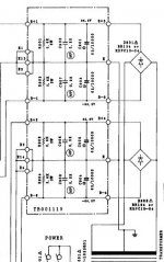
I would like to confirm if running two bridges like shown in the above schematic, is OK.
I think the blowing the rectifier issue is in the context of doing a configuration like shown below. ie can't do that with a center tapped transformer, which I agree.
As long as it is safe, then can play off of the two possible configurations. I have a bunch of 80V/10K caps, so a 2X3 config might fit, but would need to jointly power both channels. Two 2X2, or 2X4 config is probably too tight for the chassis.
Attachments
FWIW: I decided to go with a split supply, like in the post directly above. I will use a common capacitor bank of 6 (2X3), which will increase it over stock by 50%. 40K -> 60K.
I also think I have a method to figure out the windings on the 545II transformer. It will eventually go into another 545II for a dual mono-block. That will be a shoehorn project. 😉
It is still not clear to me if the first diode bridge configuraton is a problem or not, so wouldn't mind some input on that. thx.
There is no problem. Its only another solution for the same issue. I would use one diode bridge because of I argued on post #2. And one diode bridge cost saved.
Yes, that is okay but not usually used because it has double the losses in the diode bridges.I would like to confirm if running two bridges like shown in the above schematic, is OK.
Ed

I suggest you also to add 0.01uF in parallel to each diode to reduce the noise generated by them.
I am planning on 0.1mfd X2's on the primary and secondary windings. I could probably add those on the chassis mounted bridges, if need be.
Be carefull with capacitors on primary winding. I've had experience, that they can short circuit, better use very high voltage type, like 1000 or 1600 volts. Maybe for 120v mains that's not problem, but for 230v yes, very high voltage spikes happen, while turning power off.
Sorry, the X2's were for bypass. Safety Cap It is for 120V Primary/40V secondary. Cap is 310V AC rated.
Such ones( yellow ) fail frequently in smps and not only , failure is partial of full loss of capacity. I think this is not suitable to be connected over primary winding. While trying absorb returning energy from winding, it fails, if transformer is powerful.
I can confirm, the second pair of orange/red wires on a GFA-545 transformer are just in parallel with the first pair. And there is one center-tap wire. With a center-tapped transformer, one bridge is all it needs. If it had two separate secondary coils, I would put a bridge on each and bring the grounds together after the filter caps. Unfortunately that's not an option with the stock transformer.
- Home
- Amplifiers
- Power Supplies
- Two Bridges and Center Tap Confusion