Stupid newbie question. I am designing a crossover for a ss 9700 and understand I need a notch filter as this isn't ferrofluid cooled. So I'd run a cap and coil in parallel with the tweeter to pass 500Hz. But I don't understand why I'd use the cap. I certainly don't want anything below 500Hz sent to the tweeter. Why a notch filter and not just a steeper crossover or cross higher? Or do I have the wrong idea altogether?
If your crossover is at least 1 1/2 octives above resonace freq. you my be ok. Ringing is what may happen and it can do some strange things to impedance and the Frequency response.
My question was meant more as "what is the theory behind using a notch filter" rather than "Can avoid it in my specific design".
The notch in question is a series LCR Zobel shunted across the driver tuned to the tweeter's F0 impedance peak with the object of flattening it, improving power handling & ensuring the high pass transfer function isn't fouled up.
As attached example; this is a 3ohm tweeter with an F0 of ~600Hz. 1.2mH, 56uF + 5.6ohms across it. Dark blue as-is, pale blue with the LCR notch on it.
2nd graph shows the FR of the tweeter assuming a 1st order filter at 1.5KHz with the LCR notch in place. The 3rd shows the FR of the tweeter assuming the same, but without the F0 impedance flattening notch. I should stress that I don't recommend 1st order at 1.5KHz, it's just an example. 😉
You can use a steeper filter & sometimes avoid the need. Likewise a higher XO frequency. Or both. These may not be practical / possible -it depends on the tweeter + general design.
Attachments
Last edited:
Why a notch filter and not just a steeper crossover or cross higher? Or do I have the wrong idea altogether?
No, you don't have the wrong idea.
Both a notch at tweeter resonance or a generally steeper filter would both serve to keep lower frequency energy out of the tweeter. The real problem comes if a low order, say first order slope is desired. The impedance bump at tweeter resonance will interact with a simple network and give a peak in input voltage. Either a conjugate to flatten the impedance or some other form of tank circuit to "de-peak" the voltage to the tweeter will let you achieve your target curve. As you go to higher slope networks this becomes less of an issue and some adjusting of values can get you around any peaking at resonance.
David S.
I often "misused" the parallel resistor of an L-pad to flatten the impedance at resonance and thus omitting an LCR circuit. Surely not "perfect", but works well IMO.
Especially with nominal 8Ohm Tweeters even rather low values of that parallel resistor can be used - e.g. something like Rdc of the tweeter.
In this way also the parallel inductor e.g. in a 2nd order high pass gets smaller.
Also this way some electrical damping (by back-emf) for the tweeter can be maintained in the cutoff region of the filter, which is useful IMO when the tweeter has high Qms (e.g. >1 which is not unusual for tweeters without ferrofluid).
The series resistor of the L-Pad can be made rather small too then.
The (series) LCR-circuit in parallel to the tweeter can be avoided then even in a 2nd order highpass and the (acoustical) transition region of the high pass will be rather smooth nevertheless.
Edit: Picture is a bit small, but it is "R2" in parallel to the tweeter, that i was talking about.
Kind regards
Attachments
Last edited:
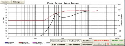
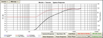
To show what speaker dave meant by interaction between
tweeter impedance peak and a 1st order filter.
Black graph on the left = 1st order filter only
Black graph on the right= 1st order filter + series RLC in parallel with the tweeter
tweeter impedance peak and a 1st order filter.
Black graph on the left = 1st order filter only
Black graph on the right= 1st order filter + series RLC in parallel with the tweeter
Attachments
Not sure why this won't link as an image:
https://www.dropbox.com/s/ej6j65uu270ipit/Crossover.png?dl=0
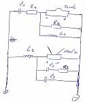
Here is a 1st order crossover with a LCR in parallel to the tweeter that acts as a notch filter. Why not just omit C2?
https://www.dropbox.com/s/ej6j65uu270ipit/Crossover.png?dl=0
Here is a 1st order crossover with a LCR in parallel to the tweeter that acts as a notch filter. Why not just omit C2?
Not sure why this won't link as an image:
https://www.dropbox.com/s/ej6j65uu270ipit/Crossover.png?dl=0
Here is a 1st order crossover with a LCR in parallel to the tweeter that acts as a notch filter. Why not just omit C2?
The resonant frequency of the notch is determined by the interaction of the capacitor & inductor, while the resistor determines the level of damping provided. RLC circuit - Wikipedia, the free encyclopedia
If you really object to LCR notches, as noted you are perfectly free to do something else if you wish.
I started my post with "stupid newbie question" because I don't have a lot of experience or knowledge in this area. I am not saying I know better than other people.
There is good simulation software available for free
which can answer most of the questions any person
interested in DIY can think of. It will save you time
and energy. You can create any frequency response
and impedance for experiment purpose. I did that
in post #9.
Jeff Bagby's Software Page
which can answer most of the questions any person
interested in DIY can think of. It will save you time
and energy. You can create any frequency response
and impedance for experiment purpose. I did that
in post #9.
Jeff Bagby's Software Page
- Status
- Not open for further replies.
- Home
- Loudspeakers
- Multi-Way
- tweeter notch filter