To protect tweeter ( Compression driver) of 50~60W from blowing, some transistor circuit is used. can u suggest some?
You need a semiconductor called a PolySwitch, an RXE110 is abought right. It goes in series with the hot lead to the compression driver. You will also need a 2R2 15W resistor, wire this in series with an 1156 automotive lamp. Wire this combination in parallel with the PolySwitch.
You can buy this ready made from Peavey for $30, or make it
yourself for less than $5.
http://www.partsexpress.com/pe/showdetl.cfm?&Partnumber=071-262
http://www.madisound.com/catalog/product_info.php?cPath=356_86_89&products_id=1015
You can buy this ready made from Peavey for $30, or make it
yourself for less than $5.
http://www.partsexpress.com/pe/showdetl.cfm?&Partnumber=071-262
http://www.madisound.com/catalog/product_info.php?cPath=356_86_89&products_id=1015
http://www.peavey.com/products/brow...egin/1/Sound+Guard?+HF+Protection+Circuit.cfm
An externally hosted image should be here but it was not working when we last tested it.
DJK,
You put me on to this a few years back. I've used it in several instances when diaphram replacement was extremely time consuming and dangerous. It works great and protects the drivers. In one church that I used it I haven't been back since to replace any of the drivers.
You put me on to this a few years back. I've used it in several instances when diaphram replacement was extremely time consuming and dangerous. It works great and protects the drivers. In one church that I used it I haven't been back since to replace any of the drivers.
A lot of un-needed fuss.
http://archives.telex.com/archives/EV/Miscellaneous/STR EDS.pdf
http://archives.telex.com/archives/EV/Miscellaneous/STR Service.pdf
I would use Schottky diodes for lower noise.
There is another note I can't find that showed adding a lightbulb across the relay contacts. Changing the series resistance higher will allow for a 2" coil, the original was for a 1" coil driver.
I recommend a 211-2 bulb for 1" coils, and an 1156 bulb for 1-1/2"~2" coils.
The relay listed is of course no longer available.
The manufacturer was American Zettler, and their current lineup contains:
9V (nominal) 18.0V (max) 405 (ohms) 6.3V (must pull-in)
pn AZ5X-1C-9DSE or AZ5Y-1C-9DSE
You can cross that to another brand if you like.
While it is only a 1A relay, it can handle 5A with a lightbulb across itself. For midrange use a 15V~18V zener should go across the coil to prevent overvoltage.
tell us the spec of the bulbs, so we can buy an equivalent.I recommend a 211-2 bulb for 1" coils, and an 1156 bulb for 1-1/2"~2" coils.
http://autorepair.about.com/od/electricalrelateddiyjobs/l/aa010502b.htm
The 1156 is a simple back up bulb in an automobile rated at 21 watts lamp power.
The 211 is an interior bulb.
I have used both per instructions from Mr. DJK in the past. The 1156 works great on the large drivers. When they are being pushed very hard the light starts to light and acts like a limiter.
Using the light only there is no interruption like there would be with a relay or poly switch.
This is perfect for any setup requiring protection and un interrupted service.
12673 GE MINIATURE LAMPS 12 volt - bulb No. 211-2BP GE LIGHTING
12673 GE MINIATURE LAMPS 12 volt - bulb No. 211-2BP GE LIGHTING "GE" MINIATURE LAMPS 12 ... ge miniature lamp, general electric miniature lamp, auto dome bulb.
I would assume that you have the same or similar across the pond.
12673 GE MINIATURE LAMPS 12 volt - bulb No. 211-2BP GE LIGHTING "GE" MINIATURE LAMPS 12 ... ge miniature lamp, general electric miniature lamp, auto dome bulb.
I would assume that you have the same or similar across the pond.
"I recommend a 211-2 bulb for 1" coils, and an 1156 bulb for 1-1/2"~2" coils.
tell us the spec of the bulbs, so we can buy an equivalent."
Standard bulb numbers, consult a catalog.
http://www.1000bulbs.com/product.php?product=1835
http://www.1000bulbs.com/product.php?product=1647
The local Gas-n-Go sells the #1156 two for $0.99, the 211-2 are a bit more at $1.29 a pair.
tell us the spec of the bulbs, so we can buy an equivalent."
Standard bulb numbers, consult a catalog.
http://www.1000bulbs.com/product.php?product=1835
http://www.1000bulbs.com/product.php?product=1647
The local Gas-n-Go sells the #1156 two for $0.99, the 211-2 are a bit more at $1.29 a pair.
I used something like the circuit in post 26 for years.
It was protecting a quite expensive Audax ring-radiator in a four-way horn-system. It worked quite well but one has to take care to not fully disconnect the load from the output of a passive high-pass crossover filter because it might damage the amplifier.
I can try to undig the circuit and maybe the layout as well (though a very unsexy one done with tape).
Regards
Charles
You'll have to wait for another 24 hours if this is OK for U. IIRC the original idea was from Elektor magazine but slightly changed.
Regards
Charles
Regards
Charles
I finally found it.
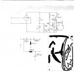
Some hints:
The reaction time is determined by the cap and the series resistor (2.2 k in this case) and the relay time constant.
The indicator LED and its parallel resistor can be left away if not needed.
For the rectifier bridge I would use some soft recovery diodes nowadays.
The small-signal PNP is of course a BD 556 and not a 546.
The sensitivity can be set with the 22k pot.
Do not switch off the load completely (as I did ) in the overload case - since a crossover highpass without load is the same as series resonant circuit - which some amps might not like.
You might want to use transistors with higher Vce capability (those were scarce 25 years ago !) than the ones I used.
Depending on what output voltage is expected from the amp in a speaker overload case - cooling of the "power" tranny might be necessary.
I also enclosed the layout (crossover & tweeter protection) but you might be faster doing a new design since I didn't properly note the component placement back then.
Regards
Charles
Some hints:
The reaction time is determined by the cap and the series resistor (2.2 k in this case) and the relay time constant.
The indicator LED and its parallel resistor can be left away if not needed.
For the rectifier bridge I would use some soft recovery diodes nowadays.
The small-signal PNP is of course a BD 556 and not a 546.
The sensitivity can be set with the 22k pot.
Do not switch off the load completely (as I did
) in the overload case - since a crossover highpass without load is the same as series resonant circuit - which some amps might not like.You might want to use transistors with higher Vce capability (those were scarce 25 years ago !) than the ones I used.
Depending on what output voltage is expected from the amp in a speaker overload case - cooling of the "power" tranny might be necessary.
I also enclosed the layout (crossover & tweeter protection) but you might be faster doing a new design since I didn't properly note the component placement back then.
Regards
Charles
Attachments
Thank u very much phase accurate.
I will only make for high pass filter. i will remove midband filter.
i will design the pcb new.
I will like to hv ur suggestions 4 good soft recovery diodes, & transistors 4 more reliability.
I will incorporate any other suggestion also.
I will add one resistor in the signal path parallel to relay for more option. This will be useful to get attenuated output after relay is on.
- Status
- Not open for further replies.
- Home
- Amplifiers
- Solid State
- tweeter ( Compression driver) protection circuit