Dear DIY Audio Members,
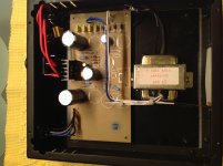
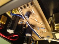
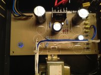
Out of curiosity I openend the power supply of my Jasmine LP2.0 phono pre-amp and was somewhat surprised to find it containing what looks like a pcb to house a "dual mono" power supply. You'll find a few photos attached (ignore the 4 missing diodes between the small yellow caps; I'm still in the progress of replacing the previously mounted IN4007 with UF4007).
Here's my question: I'm sort of tempted to "fill in the blanks", i.e. Realize the dual mono stage and upgrade filter capacitors and capacitance overall, but wanted to get your view... does this pay off? If yes, what changes/mods would you recommend me to do?
Whilst having some soldering experience and understanding the electronics basics (sticking to mere upgrades of components), I'm a layman when it comes to circuit build. Nonetheless, I felt with a little bit of help and advice this might be an attemptable small project, where I thought I can't screw up too much (happy to stand corrected though ;-).
Thanks in advance for your tips and recommendations!
Best regards, Andre
Attachments


To build a dual supply you need a dual transformer i.e. separate secondaries. Attempts to run two separate PSUs from one secondary almost always end in tears. The reason is simple: two things cannot be both separated and connected. A single PSU can supply a stereo circuit; two completely separate PSUs can supply each channel of a stereo circuit; what doesn't work is something in between as the grounding goes horribly wrong.
Dear DF96,
The actual amplifier stage (in a separate housing) is also designed with two identical circuits for left and right channels and the interconnect runs seperate ground and power lines for each channel, so in theory this should work.
Kind regards,
André
The actual amplifier stage (in a separate housing) is also designed with two identical circuits for left and right channels and the interconnect runs seperate ground and power lines for each channel, so in theory this should work.
Kind regards,
André
Are you sure this is not a PCB that can produce + and - voltages ? Check pinout of the lacking chip with the one that is soldered and compare with datasheet. It seems kind of a generic PCB that is reused for this purpose.
If layout is also for a positive regulator then maybe you can feed L + R separately. However, you do need to check all wiring though and check if things are different from how they look. I think it uses 2 different voltages and that the voltage regulator for the lowest voltage was cancelled (cost cutting). There is a connection on the PCB linking the 2.
My advice: put some time in checking how they've done it. Make a drawing/schematic and improve the skills.
edit: after checking i see they omitted a reg and used the only filtered voltage for some purpose. Measure voltages too while you are at it.
Last edited:
DF96 and Jean-Paul,
You are right... it pays off to check properly. I traced the wiring back to the amp and discovered that one of the pairs ground and plus wires merely supplies the front lighting LED panels on each box, so I was mistaken in my assumption that it could feed two channels. Looks like the Chinese indeed selected a standard PCB off the shelf for this purpose. I'm learning with every question and every bit of advice here... thanks 🙂
Do you feel there is any benefit to be had in upgrading filter caps and overall capacitances or is this just a waste of money? I do believe that the uf4007 rectifyer diodes will help over the IN4007 though...
Make a drawing and then decide what to do. Better caps never hurt and they make you feel better 😉 Pana FC/FM, Silmic II are OK. BTW it seems they used quite good quality caps. I would build CLC or CRC config before the reg. Again, it seems that the board is prepared for that. More important is the choice of reg...you sure keep us waiting Herr Musik !
If the reg is 78XX: many new regs are better than 78XX although some 78XX can be very good. Dinosaur of the same era LM317 is better than 78XX. TPS7A4700 seems to be the reg of choice for your purpose with only 4 µV noise:
http://www.ti.com/lit/ds/symlink/tps7a47.pdf
For a phono amp this won't be a waste of money. DIYINHK sells dual boards, you need to check of you only need 20...28V DC (I am gambling here, your transformer is 28V + 5V) and if those boards can be changed to higher output. Most use them for 3.3V/5V. With TPS7A4700 you will need another transformer as the current one generates at least 42V DC. Max. input voltage of TPS7A4700 is 36V. Max. output voltage is 20.5V so you will need to .....
Or cheap solution (no onboard rectifier) and how are you going to solder the chip? You can mount this small PCB on your PCB and use the old rectifiers but optically it will hurt eyes.
https://oshpark.com/shared_projects/9CqR0CfN
Better but it needs a 50V filter cap and setting for right voltage that you still have to measure....
http://www.ebay.ca/itm/252501322400?rmvSB=true
Last edited:
So:
- measure voltages on the cables going to the preamp
- measure current in each string with al options enable and all LEDs lighting (if applicable)
- check reg type
- make drawing
Then report back.
If it was my device I would really like to design/build/buy a way better PSU.
- measure voltages on the cables going to the preamp
- measure current in each string with al options enable and all LEDs lighting (if applicable)
- check reg type
- make drawing
Then report back.
If it was my device I would really like to design/build/buy a way better PSU.
Last edited:
Dear Jean-Paul, you're plunging me off into the deep end of the pool ;-) But this is good as I honestly want to learn and maybe with some guidance here will get the jist of basic electronics and circuit design. I've taken a stab at drawing up the PSU circuit... took me a couple of attempts and apologies if I have used a wrong symbol anywhere (possibly for the mosfet).
I have discovered that the transformer coil for the 28V supplies the amp circuit and that the 8V coil supplies the secondary circuit, which is completely independent and only supplies the LED front lighting of both units... I've ignored that one for now and it is not included in my drawing. The output is a screw-on 4-pin connector reading 24VDC out, which supplies the amp (the 2 connections from my drawing plus the two for the LED).
I have discovered that the transformer coil for the 28V supplies the amp circuit and that the 8V coil supplies the secondary circuit, which is completely independent and only supplies the LED front lighting of both units... I've ignored that one for now and it is not included in my drawing. The output is a screw-on 4-pin connector reading 24VDC out, which supplies the amp (the 2 connections from my drawing plus the two for the LED).
Attachments
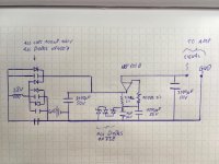
I may add one constraint to my project, which is space: I want to keep the casing, which doesn't leave much space, i.e. max. 4cm of height for components.
Yes it is clear. The Symbol of the MOSFET is wrong but is does not matter too much. Very simple PSU. I would use CLC filtering after the rectifiers. Better is to build a new PSU like:
http://www.amb.org/audio/sigma11/
10 µV noise is low noise indeed.
http://www.amb.org/audio/sigma11/
10 µV noise is low noise indeed.
Last edited:
Dear Jean-Paul, thanks a ton for this recommendation. That PSU design looks pretty straightforward to realize and I think I'll try my luck at it 🙂
Check if it fits in your case please. Also think of a solution for the LED PSU. I use Velleman K1823 for such simple tasks. Very small and cheap (less than 10 Euro) and price justities use of better caps. Don't forget to order M3 standoffs for both boards.
Please support Ti Kan of AMB.org by buying an original PCB and not a shameless copy from the "bucht".
* for easier building please determine where you will mount them in the case and drill 3.5 mm mounting holes using the bare PCBs as template. 4 pencil dots per board and you can drill without further hassle. Also look careful that wires of 24V and 5V outputs and the transformer wires are long enough when you determine where the boards will be mounted. Just saying!
Last edited:
- Status
- Not open for further replies.
- Home
- Amplifiers
- Power Supplies
- Tuning a Jasmine LP2.0 Power Supply