A little over a year ago I posted here about a hum which was "created" in the MAG PHONO section of a Heathkit AA32 after a complete rebuild. There were lots of suggestions but the problem persisted but I have yet to try an outboard 6V DC power supply to the tube filaments. Since the tubes functioned fine before the rebuild on internal 6V AC power, I understand no reason why it should not continue doing so.
I had the good fortune to become acquainted with someone knowledgeable about tubes and with a well equipped bench. He picked away at it over several weeks but could not determine where the MAG PHONO hum originated. One of his suggestions was to remove the Orange Drop capacitors connected to V1 (the pre-amp tube) which I used to replace what the assembly manual called "tubular capacitors" and re-install the old ones. I did this and the hum appeared to lessen somewhat.
(As a side note, after re-installing the original caps, only one channel is working. Probably a bad solder connection or maybe one of the old, re-installed caps is bad. I shelved this project for a while and will return to it later).
One of my thoughts after encountering this hum after rebuild was that modern components may be "too good" for an old amplifier's design.
Something that puzzled me during the re-build was that the assembly manual stressed the importance of installing the "tubular capacitors" exactly as shown. That was in reference to those original caps having a "bar" on one end which to me indicates polarity. Unless I am mistaken, those "tubular capacitors" are a film type which are therefore, generally speaking, non-polarized. With that assumption, I installed the Orange Drops without heed to whether one side was PLUS and the other MINUS.
Attached are 2 photos of one of the original "tubular" caps to show what I meant about the "bar" at one end. Is it possible, that I should have tried sourcing a polarized mylar or some other film capacitor and does such a thing exist?
Attachments
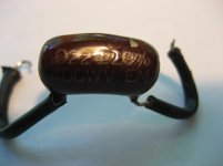
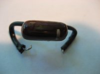
It isn't polarized. The stripe at one end indicates "outside foil".
A cap is two layers of a conductor - in this case a thin metal foil - with a dielectric insulator between. The that is rolled up to make a compact part. One leyer of foil will then wind up on the outside of the roll. The wire lead to that one is thus the outside foil.
A cap is two layers of a conductor - in this case a thin metal foil - with a dielectric insulator between. The that is rolled up to make a compact part. One leyer of foil will then wind up on the outside of the roll. The wire lead to that one is thus the outside foil.
Yes, when I was poring over info about capacitors (thinking the new Orange Drops could be to blame), I read of the possibility that the outside layer may shield out induced noise such as hum. Problem was, there was conflicting speculation about how to identify which lead of a modern capacitor comes from the outside layer.
If a manufacturer, Heathkit in this case, specifies positioning of a film capacitor, would this be the reason?
If a manufacturer, Heathkit in this case, specifies positioning of a film capacitor, would this be the reason?
Last edited:
If someone specifies which way round to wire a film cap then either
1. they don't understand what they are doing
or
2. they want the outer foil connected to the right circuit node - usually to reduce hum.
In the case of Heathkit I would assume option 2 is true.
Normally the outer foil should connect to the lower impedance node - could be ground if it is a decoupling or filter cap, or the anode if it is a coupling cap.
If, as seems to be the case here, the cap can pick up significant hum then it is not only necessary to get it the right way round but also in the right position - distance from nearby AC conductors matters. Keep it well away from heater wiring, for example. This sort of thing was routine in the 1950s, but modern audio enthusiast have forgotten these old skills.
To find the outer foil connect the cap to an amp input. Hold the cap in your fingers. Note the level of hum. Turn the cap around. Try again. Loudest hum means the outer foil is connected to the amp input. You can use a scope instead of an amp if you have one.
If someone specifies which way round to wire a film cap then either
1. they don't understand what they are doing
or
2. they want the outer foil connected to the right circuit node - usually to reduce hum.
In the case of Heathkit I would assume option 2 is true.
Normally the outer foil should connect to the lower impedance node - could be ground if it is a decoupling or filter cap, or the anode if it is a coupling cap.
If, as seems to be the case here, the cap can pick up significant hum then it is not only necessary to get it the right way round but also in the right position - distance from nearby AC conductors matters. Keep it well away from heater wiring, for example. This sort of thing was routine in the 1950s, but modern audio enthusiast have forgotten these old skills.
To find the outer foil connect the cap to an amp input. Hold the cap in your fingers. Note the level of hum. Turn the cap around. Try again. Loudest hum means the outer foil is connected to the amp input. You can use a scope instead of an amp if you have one.
No scope, so amp input it is & thank you for that tip.
There is little room inside the chassis so the caps are pretty much in the same place as the originals. I'll mark the new caps' ends using your method and re-install where I've reverted back to the originals.
Come to think about it, I did once try reversing those new Orange Drops attached to pre-amp tube V1 seemingly with no improvement. There are others in the amp not directly connected to V1 and although they do not seem associated with the hum problem, I should probably then check them and re-position as necessary.
When I rebuilt the amp, I replaced all the wiring, following the original assembly manual's routing diagram and space dictates where it goes. That is what made me think those new capacitors were more sensitive to picking up AC hum than the originals were.
The degree to which there is a right way to hook up a cap depends on its role and its reactance as compared to other circuit parameters.
The shielding provided by the outside foil can be very significant with bypass caps, but is often far less significant for coupling caps since the cap's impedance at low audio frequencies should already be low. IOW both leads of the capacitor can be thought of as being shorted together for AC.
It may be possible that you are trying to suppress hum to a degree that was not intended in the original design.
I'm not trying to discourage you, but if you are going beyond the original design parameters, some out-of-the box thinking may be needed, and simply getting the outside foil hooked up optimally may not be sufficient. You may have to identify and correct the source of the hum.
Let's assume a net anode impedance of 25k (i.e. anode with anode resistor in parallel). Grid resistor of next stage is 1M. A 22nF cap will give LF rolloff at 7Hz, so big enough for many purposes - people did not expect LF to go down to 1-2Hz in the 1950s and 60s. At 60Hz the cap will be -j120k in impedance.
If the outer foil is connected to the anode then an incoming hum current (via a small stray capacitance) would see an impedance of just below 25k, and little attenuation from there to the following grid.
If the outer foil is connected to the grid then the hum current would see an impedance of about 25k-j120k - about 122k in magnitude. The 1M in parallel will knock it down a bit but it will still be significantly greater than 25k - say 100k.
So we have a hum difference of about 12dB just by reversing the coupling cap. This is because for coupling purposes the cap reactance merely has to be small when compared with the grid leak resistor - but may still be large compared with the anode impedance.
- Status
- Not open for further replies.
- Home
- Design & Build
- Parts
- Tubular capacitors in Heathkit AA32 amplifier