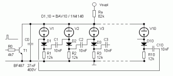
Been a while since I did a tube project. Sit down, relax, and enjoy. 🙂
Blinkenlites - Album on Imgur
Schematic: https://www.seventransistorlabs.com/Images/Tube_Shift_Register.pdf
Tim
Blinkenlites - Album on Imgur
Schematic: https://www.seventransistorlabs.com/Images/Tube_Shift_Register.pdf
Tim
Attachments
Last edited:
Because it's fun, of course! I didn't want to depend on the behavior of neon bulbs, partly because I have surprisingly few in the bin here... and they're hard to use. Notice the attached circuit is one-hot only, as best I can tell -- while this circuit does any combination (including the one degenerate state all pure maximal-length LFSRs have). Also easier to synthesize logic -- note V6 and V7 form an XOR gate.
It also generalizes for other outputs. Example, add a pair of 5687s to drive small incandescent bulbs, or 2D21s to drive FWB + transformer + bigger loads, etc.
Notice the plate resistors (and cathode tail) are dimensioned to give very similar V_OH and V_OL from both sides. Balance is important in this circuit. The 1Meg resistors must be 1% or better!
Vacuum tubes also can run faster, though with the exact method and values I've used here, it doesn't go above some kHz, and obviously, not like it has any blinkenlights value anywhere near that fast. 🙂 Whereas neon tubes top out in the 10s, maybe 100 kHz, but a more optimized circuit like this (though maybe requiring up to twice as many tubes?) could run up to a few MHz.
Or transistors, or logic gates, but if I was going to do that, I'd go all in and slap an LCD on an MCU, like this: 🙂
The world needs more raycaster graphics engines on ATMEGA chips! - Album on Imgur
Tim
