So I believe I busted my rare CK1006 gas rectifier 🙁. I have a 3DG4 to replace it (without the brilliant blue glow though...) but I don't want to hook it up until I understand why I broke the first tube
I'm building one channel of my new amp for testing and have begun paying attention to common grounds. It seemed reasonable to start from the ground from the wall socket, which I have connected to the case of my main transformer.
I connected my CK1006 as shown in the attached use circuit, but I made sure to have the ground for the heater connected to my common ground, as well as the center tap (in the rectifier use circuit). This common ground idea was also done in my reference schematic which is also attached to this post.
So, where did I go wrong? My hunch is that somehow the high voltage was applied directly across the CK1006 heater based on the common ground (it flashed very bright before it died). This would be because the heater actually behaves as the cathode in this circuit, so if one side is grounded and the other gets the rectified high voltage, then it would break.
Is my logic sound? If so, I would need to find another way to create a common ground...
Attachments
The heaters of your rectifiers should not be grounded. They need to float. check the tube specs. for heater / cathode voltage. If its a directly heated cathode you are shorting the high voltage to ground. Remove the ground to the rectifiers. It needs to float.
I see, so maintain a common ground for everything else (including heaters for other tubes) but the rectifier should have a floating heater for the reason we discussed
As others already said: The heater winding for the rectifier tube *must not* be referenced to ground. As shown in the schematic, the rectified HV is shorted to ground, leading to severe over-current conditions and subsequent destruction of the rectifier tube and the mains transformer HV winding.
Apart from that, it is no good practice to connect one side of the heater windings for the audio tubes to ground, this will cause hum issues. The ground reference should be made via the center tap of the heater windings. If no center tap exists, an 'artifical' center point can be derived via two appropriately sized resistors.
Rundmaus
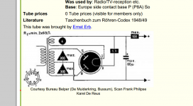
CK1006 filament voltage MAXIMUM is 1.75V!
6.3V burning out the heater!
It's not necessary to heat the CK1006, if anode current large enough.
"Cathode may be either directly or ionically heated; ion heating only possible for output current in excess of 70 mA. "
6.3V burning out the heater!
It's not necessary to heat the CK1006, if anode current large enough.
"Cathode may be either directly or ionically heated; ion heating only possible for output current in excess of 70 mA. "
Last edited:
it is no good practice to connect one side of the heater windings for the audio tubes to ground, this will cause hum issues. The ground reference should be made via the center tap of the heater windings. If no center tap exists, an 'artifical' center point can be derived via two appropriately sized resistors.
Rundmaus
If I am to understand you correctly, I should ground the center tap of my filament transformer. This sounds similar to an anti hum potentiometer. As it turns out I do have a center tapped filament trans, should I ground the center and remove the anti-hum pot?
PS: Don't worry, the schematics I show are only for reference. I did use 1.75V and so the breakage was due to my grounding as we mentioned
Yes,
that is what a hum potentiometer does. It provides a 'variable' ground point to optimize hum. But a fixed resistor pair or the winding center tap is still much better than grounding one end of the winding.
If there is a hum pot in place, use it. My advice to ground the center tap referred to the schematic you posted, with the heaters connected to ground on one side.
Oh nice, I'm glad that I figured that out 🙂
I am building this amp from scratch so I can decide to either have anti hum pot or center grounding. Sounds like you recommend a potentiometer?
I am building this amp from scratch so I can decide to either have anti hum pot or center grounding. Sounds like you recommend a potentiometer?
I did not build enough tube stuff to recommend a certain approach. Better wait for more experienced users to answer that question.
I just thought there's a reason the original designer put a humpot in there.
Rundmaus
I just thought there's a reason the original designer put a humpot in there.
Rundmaus
Oh nice, I'm glad that I figured that out 🙂
😀🙄..and me..LOL
Regards
M. Gregg
I understand. Thanks to all of you for the help, I greatly appreciate it.
I think an anti-hum potentiometer might be best since it offers adjustability. If anyone else has a good idea please let me know, but I will go forward with this for my prototype
I think an anti-hum potentiometer might be best since it offers adjustability. If anyone else has a good idea please let me know, but I will go forward with this for my prototype
A 'hum pot' is good. You can null much of the filament hum which may be introduced into the amplifier due to stray coupling between the filament circuit and low-level amplifier stages.
Oh right, I hadn't considered the low level stages since my reference only has anti hum for the last stage.
Should it be a global pot for all three stages, one for each, or just one for the last stage as shown in the reference schematic
Should it be a global pot for all three stages, one for each, or just one for the last stage as shown in the reference schematic
I'd build it without the additional hum pot. You can add it if necessary.
I agree. Use the CT available on the heater winding to ground. You would only lift the CT and use a hum pot if you were going to put a DC bias voltage on the heaters.
20
The pot on the output stage is not a hum pot. It adjusts the operating point of the tube. I just realized it when I looked at the schematic again.
The filament of the output tube operates from a d.c. source. The pot (actually a hefty wirewound adjustable resistor) is adjusted to bias the tube properly.
The filament of the output tube operates from a d.c. source. The pot (actually a hefty wirewound adjustable resistor) is adjusted to bias the tube properly.
Interesting, I've heard there are reasons to have DC bias for anti hum as well...
It would seem strange to adjust biasing by changing the heater voltage. Wouldn't that just change the temperature since that is the only function of the filament in the 811?
It would seem strange to adjust biasing by changing the heater voltage. Wouldn't that just change the temperature since that is the only function of the filament in the 811?
Last edited:
I was wrong. For some reason, the variable resistor is being used to balance the ground connection point of the filament. It may very well act as a hum pot. I'm not quite sure what I was thinking when I mis-read the schematic. Nonetheless, it's a strange arrangement. You can't expect much power from the amplifier with such low plate voltage on the 811 tube. Have fun with your project.
- Status
- Not open for further replies.
- Home
- Amplifiers
- Tubes / Valves
- Tube Rectifiers and Common Grounds