Dear all,
i am currently working on my 6v6 parallel tube amplifier and faced some difficulties with the rectifier.
I wanted to build this rectifier with a hammond ao20927 trafo, with a 400-0-400v output. Sine one if these old trafos is short cirquited, i replaced them with edcors.
The rectifier is powered with an edcor xpwr149 transformer, at 240v. Outputs are acc. to edcor 400-0-400v. Measured input voltage 234V, output voltage 411-0-411v.
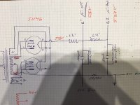
The voltages measured after parallel loading of 2 5u4g tubes for rectification was 528v dc, the henry transformers and the capacitors do not measurably reduce the output voltage of the rectification chain/dc power supply chain, see schematic for it.
I do not understand the reason for this, with the original hammond transformer, the supply delivered 360 respectively 340v dc.
Can you give me an advice hiw to reduce the voltage to approx. 380 and 350v dc without too much loss of power? I assume that the henry transformers are not made to withstand these high voltages, I plan to place a 600ohn 100w resistor prior to the first henry to get a voltage drop to approx. 380v followed by a 160ohm 25w to get the final 340 or so. Will this work?
As bleeders I used 500k/25w for the 100uf cap and 1000k for the 30uf cap. Do i need both bleeder steps or will the last one do it too?
Thanks for your help
i am currently working on my 6v6 parallel tube amplifier and faced some difficulties with the rectifier.
I wanted to build this rectifier with a hammond ao20927 trafo, with a 400-0-400v output. Sine one if these old trafos is short cirquited, i replaced them with edcors.
The rectifier is powered with an edcor xpwr149 transformer, at 240v. Outputs are acc. to edcor 400-0-400v. Measured input voltage 234V, output voltage 411-0-411v.
The voltages measured after parallel loading of 2 5u4g tubes for rectification was 528v dc, the henry transformers and the capacitors do not measurably reduce the output voltage of the rectification chain/dc power supply chain, see schematic for it.
I do not understand the reason for this, with the original hammond transformer, the supply delivered 360 respectively 340v dc.
Can you give me an advice hiw to reduce the voltage to approx. 380 and 350v dc without too much loss of power? I assume that the henry transformers are not made to withstand these high voltages, I plan to place a 600ohn 100w resistor prior to the first henry to get a voltage drop to approx. 380v followed by a 160ohm 25w to get the final 340 or so. Will this work?
As bleeders I used 500k/25w for the 100uf cap and 1000k for the 30uf cap. Do i need both bleeder steps or will the last one do it too?
Thanks for your help
Attachments
Last edited:
Did you measure the B+ voltages with a sufficient load?
Choke input supplies deliver approx. 0.9*V_ac when loaded with the design current draw. Below a critical minimum current depending on the choke inductance and other parameters, the voltage will rise to approx. 1.4*V_ac, which seems to fit your measured values.
Be careful with testing valve supplies without a suitable load, caps and other components might not be able to cope with the higher voltages.
Regards,
Rundmaus
Dear all,
i am currently working on my 6v6 parallel tube amplifier and faced some difficulties with the rectifier.
How much current (in mA) is this power supply required to deliver?
I agree with Rundmaus - you need to load the power supply either with the amp & tubes or with a suitable resistor load. I don't know if you are doing this already?
I there a reason you selected a high wattage resistor for that 500k bleeder?As bleeders I used 500k/25w
My quick calculation shows under 1W power dissipation, so a 5W or even 2W resistor would be big enough.
For calculating bleeder resistance, this site (or a similar one) may be useful:
Capacitance Discharge Calculator | Engineers Edge | www.engineersedge.com
The correct formula for Choke loaded power supplies is critical inductance = 350/mA load.
For example, with a 150mA load, the critical inductance is 2.33 Henry.
If the first choke is less than the critical inductance, as was said earlier in this thread, the voltage will rise (up to as much as 1.4x the ACVrms).
There is a diode drop in the rectifiers that reduces the final voltage, but it depends on the mA draw of the load.
The time constant of 500k Ohms and 100uF is 50seconds (too long).
After the power to the supply is turned off, in one time constant, the supply will decay in voltage to 63% of the original voltage.
So, if the supply is 400V, in one time constant (50 Seconds) it will decay 0.63 x 400 = 252V drop.
400V - 252V = 148V.
After 100 seconds it will decay another 63%: 148 x 0.63 = 93.2V.
148V - 93.2V = 54.76V
After 150 seconds it will decay another 63%: 54.76 x 0.63 = 34.49V
54.76V - 34.49V = 20.26V.
After 150 second, it is now relatively safe to touch, but do not short out the capacitors with your soldering iron or a wire, you will still draw an arc.
As you can see, it might be a good idea to use a more robust bleeder.
I use 2 each 25k Ohm 5 Watt resistors in series as a bleeder. That works for 400V supplies. If you can trust the second choke not to open, you could put the single bleeder across either the first or second capacitor.
What if a choke opens?
Well, incase there is a failure of one of the parts, I always check across all the capacitors with a DMM to be sure they are discharged.
Thanks for all your answers, i measured the power supply as on the schematic, without additional loads with a 1000v meter.
I chose the high wattage bleeders since i had them around. But I agree, the voltage drop after shut down takes approx. 2 minutes to 0volts, which is long, and should be corrected.
I have calculated the resistors with the tool in the link, 37 Watt for the 600 should already be good, can I use my 100watt anyways?
The load of the transformer is 250mW. The original load of the hammond ao20927 is not known.
Thanks
What load of the transformer is 250mW?
I can't follow what the 37 Watt, 600, and 100 Watt are describing.
Please give us some more schematic(s), not just a written description.
And what is this B+ powering?
I can't follow what the 37 Watt, 600, and 100 Watt are describing.
Please give us some more schematic(s), not just a written description.
And what is this B+ powering?
Sorry, it is a typo, 250mA is the load of the transformer at 400v ac. Calculated dropping resistors are ordered. Thanks for the help.
I re-read, and finally noticed that you are going to use the 600 Ohm resistor and 160 Ohm resistors to drop the voltage. I was not focused on that, sorry.
(0.25A)Squared = 0.0625
600 x 0.0625 = 37.5 Watt, yes use at least a 100W resistor there.
0.25A x 600 = 150V drop
(0.25A)Squared = 0.0625
160 x 0.0625 = 10 Watt, yes use at least a 25W resistor there.
0.25A x 160 = 40V drop
410Vrms = 580Vpeak
Drops: 150V, 40V = 190V
580 - 190 = 390V
5U4G drop 44V @ 225mA = ~ 196 Ohms
5AR4 drop ~ ?
But you have the rectifiers in parallel, for more total current, but only 125mA/tube.
You might have 30V drop.
390V - 30V = 360V
Then there is the drop due to the DCR of the 2 chokes. You are getting real close to the voltage you want.
(0.25A)Squared = 0.0625
600 x 0.0625 = 37.5 Watt, yes use at least a 100W resistor there.
0.25A x 600 = 150V drop
(0.25A)Squared = 0.0625
160 x 0.0625 = 10 Watt, yes use at least a 25W resistor there.
0.25A x 160 = 40V drop
410Vrms = 580Vpeak
Drops: 150V, 40V = 190V
580 - 190 = 390V
5U4G drop 44V @ 225mA = ~ 196 Ohms
5AR4 drop ~ ?
But you have the rectifiers in parallel, for more total current, but only 125mA/tube.
You might have 30V drop.
390V - 30V = 360V
Then there is the drop due to the DCR of the 2 chokes. You are getting real close to the voltage you want.
This is off topic a bit..my apologies...
Does it make any difference how the two rectifier tubes are connected to the power transformer ?
a) as in the schematic above, with one tube connected to each end of the HV winding
b) with the two rectifiers connected 'in parallel' , just doubling the single-tube arrangement...
Does it make any difference how the two rectifier tubes are connected to the power transformer ?
a) as in the schematic above, with one tube connected to each end of the HV winding
b) with the two rectifiers connected 'in parallel' , just doubling the single-tube arrangement...
Attachments
There can be a difference. Your diagram shows the full AC secondary between both anodes. Depending on the rectifier, it may be better to have both anodes at the same potential, as per the original schematic. In your method, the peak cathode current per valve is lower which may offer an advantage. Note that the current per anode is the same in both cases.This is off topic a bit..my apologies...
Does it make any difference how the two rectifier tubes are connected to the power transformer ?
a) as in the schematic above, with one tube connected to each end of the HV winding
b) with the two rectifiers connected 'in parallel' , just doubling the single-tube arrangement...
Thanks - that makes complete sense to me.🙂There can be a difference. Your diagram shows the full AC secondary between both anodes. Depending on the rectifier, it may be better to have both anodes at the same potential, as per the original schematic. In your method, the peak cathode current per valve is lower which may offer an advantage. Note that the current per anode is the same in both cases.
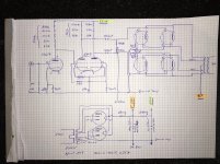
I measured the voltages under load, and you are right...
With the 5U4G it is the following voltages, for B+ 283V and for the last point still 281V.
With a 5AR4 it is 293V for B+ and for the second point 291V
This is the same in both of the power supplies (there are 2 of them).
I find this rather low.
Attached you will find a full schematic of my project.
I am currently facing several problems with it, but will open a new thread for this.
Attachments
- Status
- Not open for further replies.
- Home
- Amplifiers
- Tubes / Valves
- Tube rectifier problem