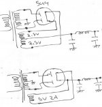
The cathode in the 5U4 and similar rectifier tubes is a resistor end to end. If you pull the DC output from the tube out of one end of the cathode the most cathode emission will be concentrated on the end of the cathode you are using as the output. Over time the cathode will wear out faster because the other end of it will not be stressed as highly and the emissive layer coating will still be fresher than the side that was connected to the load. By using a center tapped filament transformer more equal cathode loading is achieved and longer tube life is the result. The center tapped filament winding costs more money to make the transformer so it is seen less often in consumer gear.
@rcavictim
thank you for detailed explanation.So go with CT filament winding!
🙂
Is there any voltage dropped at the filament winding?It's like a choke.
But with 5 - 10 turns of wire (I guess) there's not too much resistance,right?
thank you for detailed explanation.So go with CT filament winding!
🙂
Is there any voltage dropped at the filament winding?It's like a choke.
But with 5 - 10 turns of wire (I guess) there's not too much resistance,right?
Voltage drop in the filament transformer winding to the B+ will be so small as to be almost immeasureable in any practical sense of the term.
I'm building a preamp and a phono right,now.I like to use tube rectifiers and Shindo style filtering.So, I'll try this CT technique.
😉
Thanks for help.
😉
Thanks for help.
Resident,
If your current requirements for the B+ are low, which wouldd be the case in a preamp, why not go with an indirectly heated cathode dual rectifier like a 6X5 octal or 6X4 miniature. Then you don't need a CT fil. xfmer. These need 6.3 volts.
If your current requirements for the B+ are low, which wouldd be the case in a preamp, why not go with an indirectly heated cathode dual rectifier like a 6X5 octal or 6X4 miniature. Then you don't need a CT fil. xfmer. These need 6.3 volts.
My preamp needs about 60mA and I'll use 1*10u and 3*220u caps and 47u near anodes of each triode.One triode at each channel.SE.
I'll go with 5U4G.
My phono needs 30mA and I'll use 1*10u and 5*100u.Shindo style(in both projects).And some small about 10-20u at each triode anode of two stages.
I'll go with 5V4.
Why with these?I'd like to have plenty of current.I'm a little bit extreme with PSUs but not with capacitance of caps.Just what is needed for uV of ripple.
Hi Resident,
I like CT shematics but have some douts here. DC current
will flow through the trans coil and it will not be substituted.
Power trans does not have a gap, you know. So. with big current
you can get distortions which hardly smoothing in filter.
Igor.
I like CT shematics but have some douts here. DC current
will flow through the trans coil and it will not be substituted.
Power trans does not have a gap, you know. So. with big current
you can get distortions which hardly smoothing in filter.
Igor.
hmmmm....
So, let's put a thin gap to power trans ,too.
🙂
But
😱
Or it doesn't matter?

I'll think it more clearly later.
So, let's put a thin gap to power trans ,too.
🙂
But
😱
Or it doesn't matter?
I'll think it more clearly later.
Konnichiwa,
???
The current will flow equally but it will flow in opposite directions through the heater winding halves, so it is cancelled
Sayonara
igormak said:I like CT shematics but have some douts here. DC current
will flow through the trans coil and it will not be substituted.
???
The current will flow equally but it will flow in opposite directions through the heater winding halves, so it is cancelled
Sayonara
Kuei Yang Wang said:Konnichiwa,
The current will flow equally but it will flow in opposite directions through the heater winding halves, so it is cancelled
Sayonara
Directions opposite - thats right. But phases different.
Current flows by pulses one polarity in different time intervals.
Would they be different polarity you'd be right.
May be (even sure that not) it is not so important, but I have
some doubts about it. 🙂 It was such a question.
Konnichiwa,
Look at it again. No matter how you resolve it, averaged over one full cycle of the mains the net of all currents is zero, nothing remains, so no problem.
Sayonara
igormak said:Directions opposite - thats right. But phases different.
Current flows by pulses one polarity in different time intervals.
Would they be different polarity you'd be right.
May be (even sure that not) it is not so important, but I have
some doubts about it. 🙂 It was such a question.
Look at it again. No matter how you resolve it, averaged over one full cycle of the mains the net of all currents is zero, nothing remains, so no problem.
Sayonara
- Status
- Not open for further replies.
- Home
- Amplifiers
- Tubes / Valves
- tube rectifier arrangement