Tube magic eye with em81-input sensitivity?!
Hello People!
I made magic eye with em81, how to increase the input sensitivity (faster blinks like on this site: https://www.youtube.com/watch?v=mAFPzBEe9b4)😉.
Otherwise this magic eye with em81 I connected to a stereo amplifier with LM3886T.
thanks
Hello People!
I made magic eye with em81, how to increase the input sensitivity (faster blinks like on this site: https://www.youtube.com/watch?v=mAFPzBEe9b4)😉.
Otherwise this magic eye with em81 I connected to a stereo amplifier with LM3886T.
thanks
Last edited:
When are you going to post the circuit?
This works with a change to r5..100k..
http://www.solderingpoint.com/projects/indicator_tube/indicator_tube.php
Remember its at 250V dc...
Here is a thread..
http://www.diyaudio.com/forums/tubes-valves/183271-magic-eye-tube.html
Regards
M. Gregg
This works with a change to r5..100k..
http://www.solderingpoint.com/projects/indicator_tube/indicator_tube.php
Remember its at 250V dc...
Here is a thread..
http://www.diyaudio.com/forums/tubes-valves/183271-magic-eye-tube.html
Regards
M. Gregg
Last edited:
Magic eye with em81 - i need schematic
Hi all!
I bought this magic eye: http://www.ebay.com/itm/One-6AD5-EM81-Magic-Eye-Tube-Audio-Indicator-Board-12VDC-Ver-/281443734293?pt=LH_DefaultDomain_0&hash=item41875a9315, it if there's a schematics (of this circuit) let's put it here.
thanks
Hi all!
I bought this magic eye: http://www.ebay.com/itm/One-6AD5-EM81-Magic-Eye-Tube-Audio-Indicator-Board-12VDC-Ver-/281443734293?pt=LH_DefaultDomain_0&hash=item41875a9315, it if there's a schematics (of this circuit) let's put it here.
thanks
Last edited:
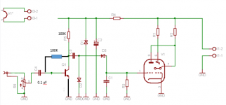
I have just had a play with the circuit in the link.
http://www.solderingpoint.com/projects/indicator_tube/indicator_tube.php
This is my new modified version..😀 (sensitivity is much better)
I modified the pin out for a different EM tube type..
C1 is now 0.047uF
Its running from the preamp input/volume control as the article says you can mod for a FET however it seems to be OK..
Regards
M. Gregg
Attachments
Last edited:
NB
I did think about using a super-alfa pair (Darlington driver)
However I think the gain might be to much..YMMV 😀
Remember to use a polypropylene High voltage input cap!
You can drive the preamp section from a LV supply..depends on what you are doing..
Regards
M. Gregg
I did think about using a super-alfa pair (Darlington driver)
However I think the gain might be to much..YMMV 😀
Remember to use a polypropylene High voltage input cap!
You can drive the preamp section from a LV supply..depends on what you are doing..
Regards
M. Gregg
Last edited:
I guess,
the problem with this sort of thing is the 250V Dc for people not using tube circuits..
So just a few ideas you could use a nixie tube supply..
Or play with a few ideas.(I haven't tried these circuits)
High Voltage DC-DC Converter Single Transistor Oscillator Circuit
Practical Transistor Circuits
Remember you still need to know what you are doing..
Shock hazard!
You could remove R4 in the circuit and feed the preamp with 30V DC <<<adds safety ...and the tube from a converter..
Which is similar to what you posted..the board is 12V DC in with a nixie type supply..so it makes the HV DC. Post 3#
I guess if it works its cheaper to just buy the board.. 😀
Regards
M. Gregg
Last edited:
Hi all!
I bought this magic eye: http://www.ebay.com/itm/One-6AD5-EM81-Magic-Eye-Tube-Audio-Indicator-Board-12VDC-Ver-/281443734293?pt=LH_DefaultDomain_0&hash=item41875a9315, it if there's a schematics (of this circuit) let's put it here.
thanks
I'm just curious why do you need the schematic? I guess you have bought the board..
What circuit did you build?
Regards
M. Gregg
Tony,
If you do run the preamp without R4 remember to remove the zener (D1)..🙄
Just thought about it..I assumed you would already know about it!
Reference post 4#
Regards
M. Gregg
If you do run the preamp without R4 remember to remove the zener (D1)..🙄
Just thought about it..I assumed you would already know about it!
Reference post 4#
Regards
M. Gregg
Last edited:
Just for fun,
for those not in the know this is interesting info regarding Sziklai and the Super-Alpha pair (Darlington driver)
I used to play with touch switches at school 😀 it just reminded me!
Oh look I can latch that transistor and then unlatch it..LMAO..have you tried the JK flip=flop its just greeeeaaatttt..😀
Darlington Transistor and the Sziklai Darlington Pair
Regards
M. Gregg
I'm just curious why do you need the schematic? I guess you have bought the board..
What circuit did you build?
Regards
M. Gregg
We need schematic (circuit) percent instead em81 have em84.🙁
Last edited:
We need schematic (circuit) percent instead em81 have em84.🙁
This is what I would try,
I would de-solder the tube socket from the board and hard wire it in like this then give it a try..if it doesn't work you can just put the socket back as it was for EM80..
NB its at your own risk..I do not know the circuit on this board.
Try it with these resistors in place first.
You could put a 10K from the board to pin 6.
Also a 150K from the board to link pin 9-7
Regards
M. Gregg
Attachments

Last edited:
- Status
- Not open for further replies.
- Home
- Amplifiers
- Tubes / Valves
- Tube magic eye with em84-sensitivity?!